Gateway, management center, and remote access system

A management center and remote access technology, which is applied in the transmission system, digital transmission system, network connection, etc., can solve the problems of unrealizable control and application, and achieve the effect of improving responsiveness

Active Publication Date: 2016-08-03
MITSUBISHI ELECTRIC CORP
View PDF5 Cites 18 Cited by
  • Summary
  • Abstract
  • Description
  • Claims
  • Application Information

AI Technical Summary

Problems solved by technology

Therefore, there is a problem that control based on complex conditions cannot be realized in a virtual home gateway that does not have the same processing power and storage capacity as the external system, and cannot be applied to this system.

Method used


Image

  • Gateway, management center, and remote access system
  • Gateway, management center, and remote access system
  • Gateway, management center, and remote access system

Examples


Embodiment approach 1

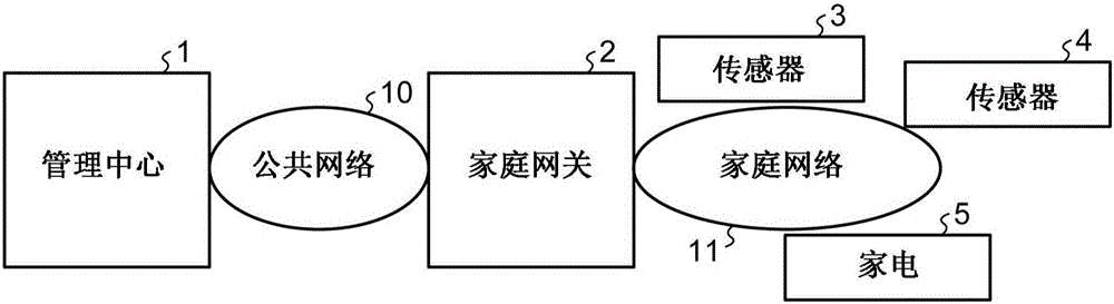
[0036] figure 1 It is a figure which shows the structural example of a remote access system. The remote access system has: a management center 1 , a home gateway 2 , sensors 3 and 4 , and home appliances 5 . The home gateway 2 as a gateway connecting the public network 10 and the home network 11 is connected to the management center 1 via the public network 10 , and is connected to the sensors 3 and 4 and home appliances 5 existing in the home via the home network 11 . exist figure 1 In the shown remote access system, home gateway 2 collects status information of sensors 3 and 4 and home appliances 5 in the home via home network 11 , and notifies management center 1 of the collected status information via public network 10 . The management center 1 can control the home appliances by being notified of the state information of the sensors 3 and 4 and the home appliances 5 located in the home. In addition, in figure 1 In the remote access system of , two sensors and one home ...

Embodiment approach 2

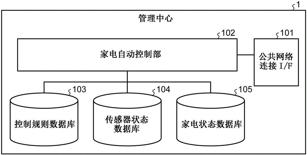
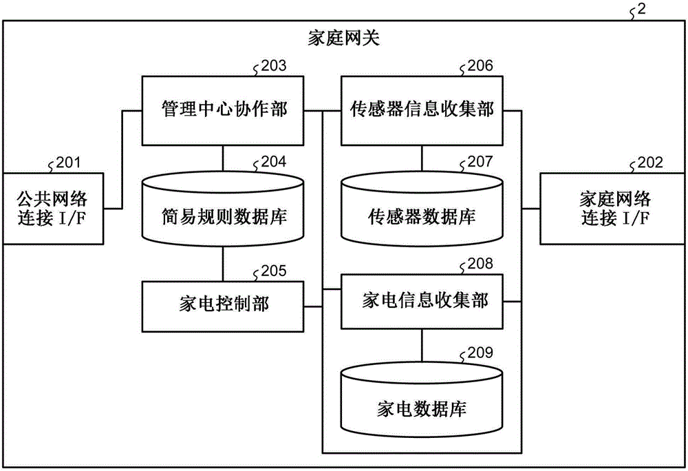
[0063] In this embodiment, a case where priorities are set in the control rule database 103 of the management center 1 will be described. In addition, the structure of the remote access system (refer to figure 1 ), the structure of home gateway 2 (refer to image 3 ) and other structures other than the control rule database 103 in the management center 1 (refer to figure 2 ) is the same as Embodiment 1.

[0064] Figure 14 It is a figure which shows the structural example of the control rule database 103 installed in the management center 1 of this embodiment. The control rule database 103 is defined as a collection of multiple control rule entries. Each rule entry is a database consisting of a rule number 1031 as identification information of the control rule, a plurality of conditions 1032 indicating the control conditions of the rule, and a control 1035 item specifying an operation when the conditions are satisfied. The condition 1032 is composed of a sensor ID 1033 s...


PUM


Abstract

A remote access system for controlling, from the outside, apparatuses connected to a home network, wherein a gateway capable of improving the responsiveness of control on the apparatuses is obtained. The present invention is provided with: a sensor information collection unit (206) for collecting information about the status of a sensor connected to the home network; a management center cooperation unit (203) for transferring the status information to a management center and acquiring, from the management center, simplified-rule information which is part of a control rule defined by the management center, the simplified-rule information including a condition that applies when controlling a home electrical appliance; a simplified-rule database (204) for managing the simplified-rule information; and a home electrical appliance control unit (205) for controlling a home electrical appliance on the basis of the simplified-rule information and the status information.

Description

technical field [0001] The invention relates to a gateway, a management center and a remote access system. Background technique [0002] With the advancement of network technology, communication devices can be realized in a low-cost and miniaturized form, and various devices are now connected to the network to operate. With the popularization of the Internet, many electronic products installed at home also have a communication function for operating in conjunction with information outside the device, instead of operating only on a single device. Currently, there is an indoor control system called a smart house, which can provide users with a comfortable living environment and suppress energy consumption by cooperatively controlling electronic appliances in the home. In a smart house, indoor home appliances are connected to a home network in order to operate in cooperation with other devices. With the spread of broadband connections in the home, devices connected to the hom...

Claims


Application Information

Patent Timeline
Patent Type & Authority Applications(China)
IPC IPC(8): H04Q9/00H04M11/00
CPCH04L12/2818H04L12/2834H04L12/2898H04M11/007H04Q9/00H04Q2209/43H04L12/66
Inventor 高田佳典
Owner MITSUBISHI ELECTRIC CORP
Why Eureka
Try Eureka