Stack column type filling formwork and using method thereof

A formwork and stacking column technology, which is applied in the field of stacking column filling formwork and its application method, can solve the problems of occupying operation time, inability to guarantee the strength in the later stage, and difficult control of the shape, so as to reduce the compression amount in the later stage and reduce the workload of formwork removal , uniform strength and reliable effect

Active Publication Date: 2016-08-10
TAIYUAN UNIV OF TECH
View PDF11 Cites 3 Cited by
  • Summary
  • Abstract
  • Description
  • Claims
  • Application Information

AI Technical Summary

Problems solved by technology

This kind of coal mining technology with filling method has achieved a good control effect on surface subsidence and environmental damage, but there are also major deficiencies: First, because the space required for filling is relatively large due to full mining and full filling, the contradiction between the supply of filling materials and the demand is relatively large. The material cost of the filling process is high; the second is because the filling workload is relatively large, which occupies the working time of the normal coal mining process, and the original production efficiency of the coal mining face is greatly reduced
[0003] The goaf partial filling methods mainly include strip partial filling and pier column partial filling. Rigid filling slides used in strip filling need to cooperate with special filling hydraulic supports for sliding, which requires high filling hydraulic support equipment; pier columns Flexible geotextile anti-seepage vacuum bags are often used to load filling materials, while paste filling materials have strong fluidity and shape is not easy to control, and flexible geotextile anti-seepage vacuum bags are easily deformed and damaged, resulting in a low rate of filling materials and unable to control the top plate The early subsidence and later strength cannot be guaranteed, and the control effect on the roof of the goaf is not ideal

Method used


Image

  • Stack column type filling formwork and using method thereof
  • Stack column type filling formwork and using method thereof
  • Stack column type filling formwork and using method thereof

Examples


Embodiment 1

[0047] 1. When the thickness of the roof is greater than 5m, the strength is greater than 100MPa and the integrity is good, calculate the initial caving step distance L according to the engineering conditions 1 , and use the safety factor method and branch area distribution method to determine the filling distance L' and the side length a of the filling cylinder (a cube structure); where: L'=L 1 -a, h is the thickness of the direct top, R T is the direct top tensile strength, q is the direct top overlying load, f cu is the compressive strength of the packed column, k 1 、k 2 is the safety factor; the calculated filling distance L at this time 1 Larger, the size a of the filling cylinder is larger, and the length of one side is generally greater than 3m;

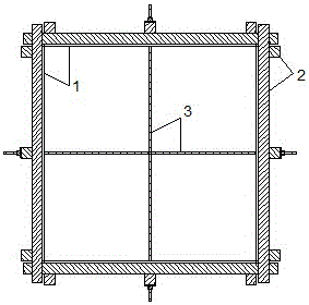
[0048] 2. Design the length a' of the filling formwork according to the size a of the filling cylinder. When the size of one side of the filling cylinder is greater than 3m, the filling formwork is designed in sections a...

Embodiment 2

[0053] 1. When the thickness of the roof is less than 5m, the strength is less than 100MPa, and the integrity is poor, calculate the periodic collapse step distance L according to the engineering conditions 2 , and use the safety factor method and branch area distribution method to determine the filling distance L' and the side length a of the filling cylinder (a cube structure); where: L'=L 2 -a, h is the thickness of the direct top, R T is the direct top tensile strength, q is the direct top overlying load, f cu is the compressive strength of the packed column, k 1 、k 2 is the safety factor; at this time, the calculated filling distance L' is small, the filling column size a is small, and the length of one side generally does not exceed 3m;

[0054] 2. Design the filling template length a' according to the filling cylinder size a, and the template height is determined with the mining height;

[0055] 3. Transport the prepared filling support frame to the filling workin...

Embodiment 3

[0059] 1. When the thickness of the roof is greater than 5m, the strength is greater than 100MPa and the integrity is good, calculate the initial collapse step distance L according to the engineering conditions, and use the safety factor method and branch area distribution method to determine the filling distance L' and the filling column ( is the side length a of the cube structure); where: L'=L 1 -a; h is the thickness of the direct roof, R T is the direct top tensile strength, q is the direct top overlying load, f cu is the compressive strength of the packed column, k 1 、k 2 is the safety factor; at this time, the calculated filling distance L is relatively large, the dimension a of the filling cylinder is relatively large, and the length of one side is generally greater than 3m;

[0060] 2. Design the length a' of the filling formwork according to the size a of the filling cylinder. When the size of one side of the filling cylinder is greater than 3m, the filling form...


PUM


Abstract

The invention discloses a stack column type filling formwork and a using method thereof. The stack column type filling formwork is arranged below a top plate, supporting frames spliced together define a cuboid frame structure on the periphery, single supporting frames or integrated bodies formed by single-side-spliced supporting frames are arranged on the two opposite faces of the formwork respectively, and every two adjacent faces are formed by perpendicularly splicing supporting frames at the edges. Each supporting frame is composed of a baffle, framework sleepers and counter-pulled anchor ropes, wherein the framework sleepers are composed of a plurality of parallel transverse sleepers and three parallel vertical sleepers, the transverse sleepers and the vertical sleepers are arranged in a perpendicularly crossing mode, and the counter-pulled anchor ropes are arranged on the vertical sleepers in the formwork center on each side. The framework sleepers make direct contact with the top plate after being spliced to support the top plate. A filling opening is formed in the upper portion of the part, on one side of the formwork, of the baffle. After filling of the formwork, the overall compressive strength of filling columns is improved, the later compression amount of the filling columns is reduced, and the top sinking amount is reduced.

Description

technical field [0001] The invention relates to a pile-type filling formwork and a method for using the same, belonging to the technical field of filling and mining. Background technique [0002] In order to control the surface subsidence caused by "three down" coal mining and the damage to the environment caused by traditional coal mining methods, coal mining enterprises have adopted the full-mining and full-filling coal mining process in recent years. This kind of coal mining technology with filling method has achieved a good control effect on surface subsidence and environmental damage, but there are also major deficiencies: First, because the space required for filling is relatively large due to full mining and full filling, the contradiction between the supply of filling materials and the demand is relatively large. The material cost of the filling process is high; the second is because the filling workload is relatively large, which takes up the working time of the nor...

Claims


Application Information

Patent Timeline
Patent Type & Authority Applications(China)
IPC IPC(8): E21F15/02
CPCE21F15/02
Inventor 冯国瑞杜献杰戚庭野郭育霞张玉江李振白锦文宋凯歌刘国艳康立勋
Owner TAIYUAN UNIV OF TECH
Why Eureka
Try Eureka