Supercharge Your Innovation With Domain-Expert AI Agents!

An automatic removal device and method for preventing iron impurities from entering a refiner

A technology of automatic cleaning and refining, which is applied in the direction of valve devices, chemical instruments and methods, sliding valves, etc., can solve the problems of equipment hazards, grinding teeth interrupted into pits, and filtration cannot be solved, so as to achieve simple operation and low cost cheap effect

Active Publication Date: 2018-02-23
SHAANXI UNIV OF SCI & TECH
View PDF16 Cites 0 Cited by
  • Summary
  • Abstract
  • Description
  • Claims
  • Application Information

AI Technical Summary

Problems solved by technology

[0002] In the pulp and paper industry, the refiner is a very important pulping equipment. The pulp enters the refiner from the inlet of the refiner, and is transported to the space between the fixed plate and the moving plate through a screw device. There are grooved grinding teeth, and the slurry is broken into fibers or fiber bundles under the action of shearing and extrusion of the grinding teeth of the grinding disc. This process is accompanied by high temperature and high pressure conditions. Once the raw material is mixed with iron wire, Iron nails and other hard iron objects, these iron impurities will instantly block the groove of the grinding teeth, and in severe cases, the grinding teeth will be broken into pits, causing great harm to the equipment
[0003] The difficulty in filtering out iron impurities such as iron nails and iron wires mixed in the slurry is that the slurry is in a state of high-speed flow. Using ordinary filter screens to filter out part of the slurry will cause part of the slurry to be filtered out, thereby blocking the filter screen and affecting The normal flow of slurry cannot solve the problem of filtering iron hard impurities in the existing refiner slurry

Method used


Image

  • An automatic removal device and method for preventing iron impurities from entering a refiner
  • An automatic removal device and method for preventing iron impurities from entering a refiner
  • An automatic removal device and method for preventing iron impurities from entering a refiner

Examples


Embodiment Construction

[0029] The present invention will be further described in detail below in conjunction with the accompanying drawings, which are explanations rather than limitations of the present invention.

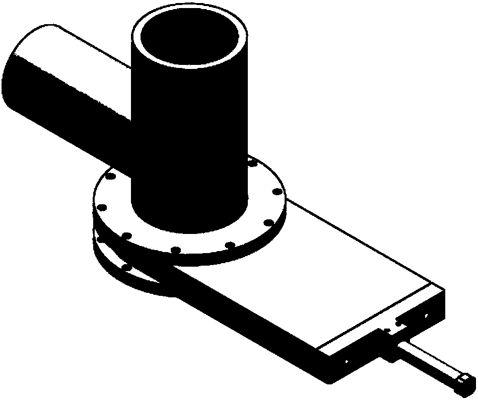
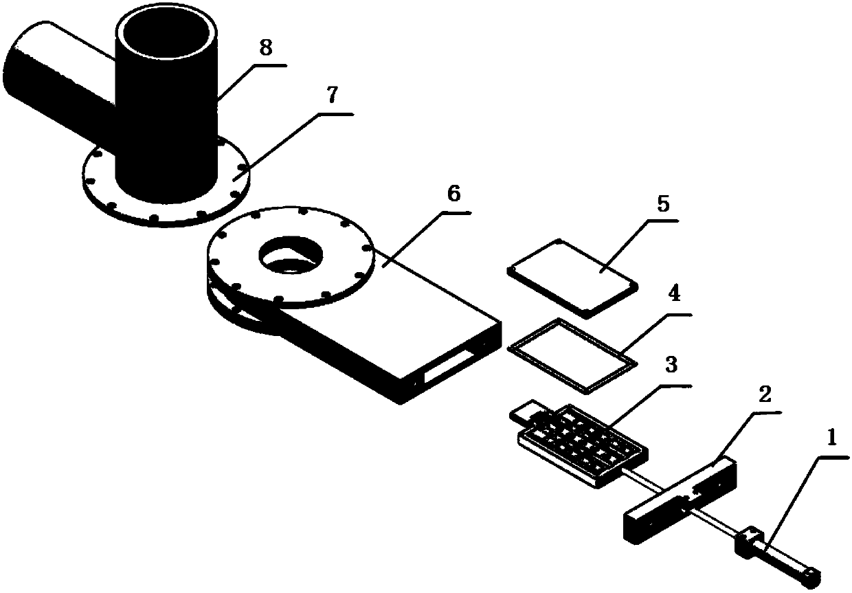
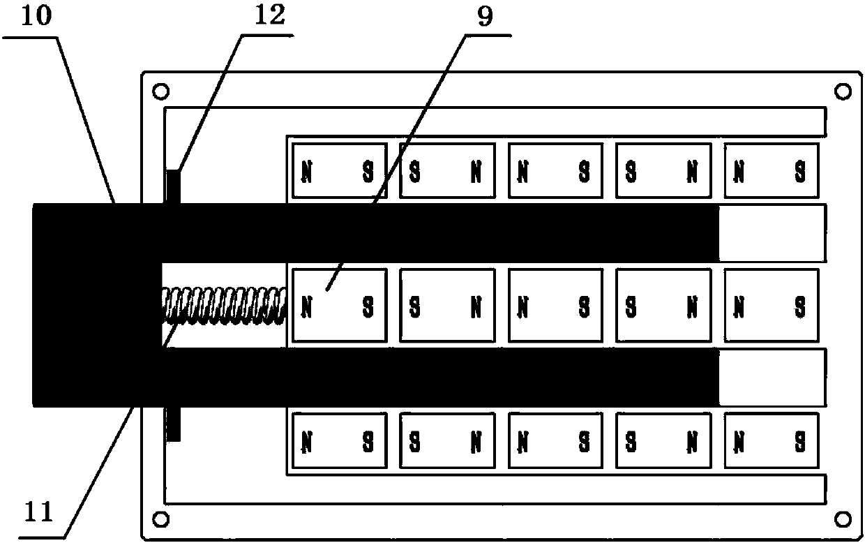
[0030] Such as figure 2 As shown, the device of the present invention includes an electric push rod 1, a push rod mounting plate 2, a core plate and a valve body 6, and the core plate includes a core plate main body 3, a sealing gasket 4 and a yoke 5; The yoke 5 mainly functions to conduct the magnetic circuit, and the sealing gasket 4 acts as a seal between the core plate main body 3 and the yoke 5 . The core plate is inserted into the valve body 6, the push rod mounting plate 2 is installed on the valve body 6, the electric push rod 1 is slidably installed on the push rod mounting plate 2, and the electric push rod 1 is fixedly connected with the core plate. Such as image 3 and 4 As shown, the core plate main body 3 includes a fixed magnetic system 9 and a moving magnetic system 1...


PUM


Abstract

The invention discloses an automatic clearing device and method for preventing iron sundries from entering a pulping machine. The device comprises a valve body, a core plate sliding in the valve body and an electric push rod for pushing the core plate to slide in the valve body; the core plate comprises a core plate body, a sealing gasket and a magnet yoke; the core plate body is arranged in a box body manner with an opening in the surface, and the magnet yoke is arranged on the opening of the core plate body in a sealed manner through the sealing gasket; a fixed magnetic system and a moving magnetic system are arranged in the core plate body; the fixed magnetic system fixed to one end of the core plate body is composed of a plurality of parallel magnetic sets arranged at intervals, and each magnetic set internally comprises a plurality of permanent magnetic blocks sequentially arranged in the magnetic pole direction, and the magnetic poles of the adjacent permanent magnetic blocks are opposite; the moving magnetic system is arranged at the other end of the core plate body in a sliding manner, and the magnetic set structure of the moving magnetic system and the magnetic set structure of the fixed magnetic system are the same; magnetic sets of the moving magnetic system are embedded in the position between the magnetic sets of the fixed magnetic system; and a spring is arranged between the moving magnetic system and the fixed magnetic system. Grinding disc grinding teeth can be effectively protected.

Description

technical field [0001] The invention relates to the technical field of pulping and papermaking, in particular to an automatic removal device and method for preventing iron impurities from entering a refiner. Background technique [0002] In the pulp and paper industry, the refiner is a very important pulping equipment. The pulp enters the refiner from the inlet of the refiner, and is transported to the space between the fixed plate and the moving plate through a screw device. There are grooved grinding teeth, and the slurry is broken into fibers or fiber bundles under the action of shearing and extrusion of the grinding teeth of the grinding disc. This process is accompanied by high temperature and high pressure conditions. Once the raw material is mixed with iron wire, Hard iron objects such as iron nails, these iron impurities will instantly block the groove of the grinding teeth, and in severe cases, the grinding teeth will be broken into pits, causing great harm to the e...

Claims


Application Information

Patent Timeline
Patent Type & Authority Patents(China)
IPC IPC(8): F16K3/314F16K27/04B03C1/30D21D5/00
CPCB03C1/30D21D5/00F16K3/314F16K27/044B03C1/0332B03C1/26B03C1/284B03C1/286B03C2201/18B03C2201/20B03C2201/22
Inventor 刘庆立汤伟王孟效胡连华王博
Owner SHAANXI UNIV OF SCI & TECH
Features
  • R&D
  • Intellectual Property
  • Life Sciences
  • Materials
  • Tech Scout
  • Unparalleled Data Quality
  • Higher Quality Content
  • 60% Fewer Hallucinations
Learn More