Continuous change type integral piston ring mechanical loading device

A mechanical loading device, the technology of loading device, applied in the direction of using mechanical devices, measuring devices, instruments, etc., can solve the problems of contact between the piston ring and the cylinder liner, and achieve the effect of ensuring elastic contact

Inactive Publication Date: 2016-08-10
海南自由贸易试验区泛亚哈工技术转移转化有限公司
View PDF11 Cites 1 Cited by
  • Summary
  • Abstract
  • Description
  • Claims
  • Application Information

AI Technical Summary

Problems solved by technology

The patent application number is 200820237523.8, which discloses a piston ring-cylinder liner friction and wear tester, and the patent application number, which is 201110041655. test, which inevitably leads to the above-mentioned piston ring and cylinder liner contact problems

Method used


Image

  • Continuous change type integral piston ring mechanical loading device
  • Continuous change type integral piston ring mechanical loading device
  • Continuous change type integral piston ring mechanical loading device

Examples


Embodiment Construction

[0015] The present invention is described in more detail below in conjunction with accompanying drawing example:

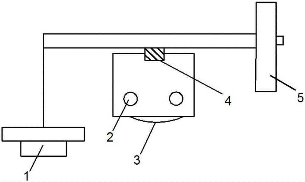
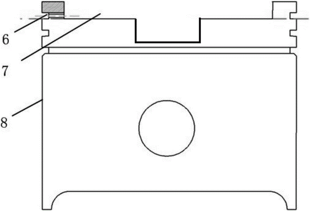
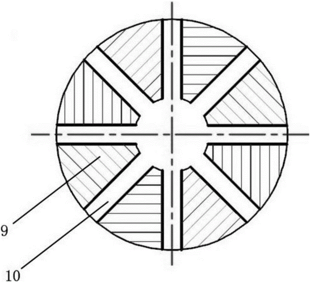
[0016] to combine Figure 1-3 , the piston 8 is the main part of the fixed piston ring and the piston ring loading device, and the piston loading device housing 9 is fixed in the loading device placement groove 7. On the piston loading device housing 9 there are 8 spring assembly placement holes 10 evenly distributed at 45 degrees in the radial direction.

[0017] to combine image 3 , the piston ring 12 is assembled between the cylinder liner 11 and the piston ring groove 6, and the push rod 14 runs through the through hole between the piston ring groove 6 and the loading device placement groove 7. The left end of the push rod 14 is in contact with the piston ring for applying load to the piston ring 12, and the other end is connected with the left spring clamp 15. The spring 16 is located between the spring clamps 15 at the left and right ends, and the right e...


PUM


Abstract

The invention provides a continuous change type integral piston ring mechanical loading device. The device comprises a piston, a loading device shell, a loading ejector rod and a connecting ejector rod, wherein the loading device shell is arranged on the top of the piston, a spring component installation hole is formed in the loading device shell, a spring component is installed in the spring component installation hole and comprises an outer spring fixture, an inner spring fixture and a spring, and the spring is located in a hollow structure formed by the outer spring fixture and the outer spring fixture; one end of the loading ejector rod is connected with the outer spring fixture, the other end of the loading ejector rod makes contact with a piston ring, a screw protrudes out of the middle of the loading device shell, an adjusting nut is installed on the screw, one end of the connecting ejector rod is connected with the inner spring fixture, and the other end of the connecting ejector rod makes contact with the adjusting nut. The integral piston ring can be loaded, uniform continuous quantitative loading of the peripheral direction of the piston ring is achieved, and relative elastic contact between the piston ring and a cylinder jacket is guaranteed.

Description

technical field [0001] The invention relates to a test device, in particular to a loading device for engine components. Background technique [0002] Piston ring-cylinder liner is one of the most important friction pairs of the engine, and its friction and wear performance directly affects the performance of the engine. At present, the main methods for evaluating the friction and wear performance of piston rings and cylinder liners are sample test method, bench test method and component simulation test method. Among them, the test parameters of the sample test method are easier to control, and the repeatability and stability are relatively good, but they are quite different from the actual situation of the piston ring-cylinder liner, and the simulation is poor; the bench test method uses a simulated load for the ignition test. The controllability of the conditions is good, and the simulation of the actual working conditions of the engine is good, but the test period is long...

Claims


Application Information

Patent Timeline
IPC IPC(8): G01N19/02
CPCG01N19/02
Inventor 卢熙群马旋郭宜斌李玩幽张成凯王东华马壬联李舒率志君李彤阳
Owner 海南自由贸易试验区泛亚哈工技术转移转化有限公司
Why Eureka
Try Eureka