
A Method for Strength Analysis and Fatigue Life Check of Splined Anti-Rolling Torsion Bar

An anti-rolling torsion bar and spline connection technology, applied in the direction of instrument, design optimization/simulation, calculation, etc., can solve problems such as a lot of time and cost, poor convergence, long analysis and solution time, etc., to improve analysis accuracy, Save R&D costs and ensure the effect of analysis efficiency

Active Publication Date: 2019-03-22
ZHUZHOU TIMES NEW MATERIALS TECH
View PDF2 Cites 0 Cited by
  • Summary
  • Abstract
  • Description
  • Claims
  • Application Information

AI Technical Summary

Problems solved by technology

However, the current finite element analysis of anti-roll torsion bars generally has the following disadvantages: (I) Due to the complex structural features of spline teeth and undercuts on the torsion bar shaft and torsion arm, C3D4 mesh elements are generally used for division , in order to obtain more accurate results, the grid is subdivided to increase the number of grids in the structure, resulting in a large number of grids, low calculation efficiency, and long analysis and solution time
(II) Due to the many contact surfaces of the spline tooth pairs, the convergence is very poor. The method of binding constraints between the spline tooth pairs affects the analysis accuracy, and the stress value at the spline tooth and the relief groove cannot be accurately calculated. Calculation accuracy is low
(III) The fatigue life check of the existing splined anti-roll torsion bar is generally carried out on the test bench. The fatigue load of the anti-roll torsion bar is designed to be 10 million times, and the loading frequency of the test bench is generally 2Hz. Therefore, the fatigue life check time of a set of splined anti-roll torsion bars is 1388 hours, which requires a lot of time and cost

Method used


Image

  • A Method for Strength Analysis and Fatigue Life Check of Splined Anti-Rolling Torsion Bar
  • A Method for Strength Analysis and Fatigue Life Check of Splined Anti-Rolling Torsion Bar
  • A Method for Strength Analysis and Fatigue Life Check of Splined Anti-Rolling Torsion Bar

Examples


Embodiment Construction

[0037] The following will take a splined anti-rolling torsion bar as an example to further describe in detail the specific implementation of the splined anti-rolling torsion bar strength analysis and fatigue life checking method of the present invention.

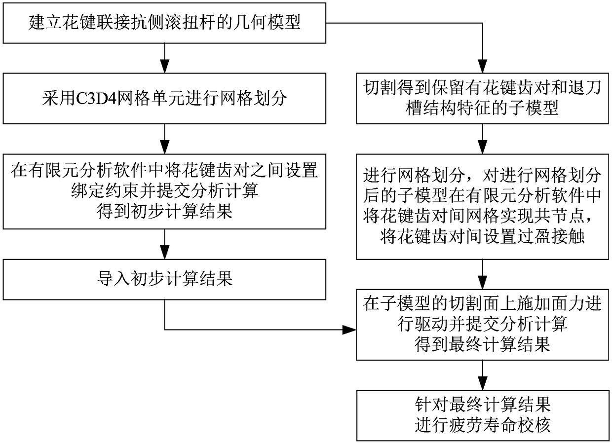
[0038] Such as figure 1 As shown, the steps of the spline connection anti-roll torsion bar strength analysis and fatigue life check method of this embodiment include:

[0039] 1) Establish the geometric model of the splined anti-roll torsion bar.

[0040] In this embodiment, step 1) specifically uses PTC Creo software to establish a geometric model of the spline-connected anti-roll torsion bar.

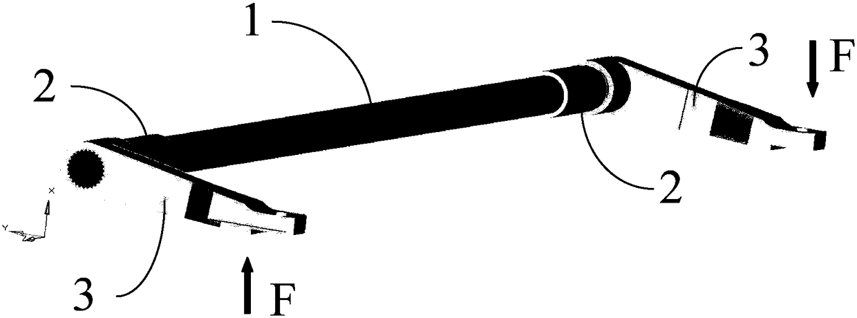
[0041] Such as figure 2 As shown, the geometric model of the spline-connected anti-roll torsion bar in this embodiment includes the torsion bar shaft 1, the mounting seat 2 and the torsion arm 3, the two sections of the torsion bar shaft 1 are fixed with a mounting seat 2, and the installation A torsion arm 3 is sheathed on the ...


PUM


Abstract

The invention discloses a method for carrying out strength analysis and fatigue life verification on spline connection anti-rolling torsion bars. The method comprises the following steps: 1) establishing a geometric model; 2) carrying out meshing, setting binding constraints between spline tooth pairs in finite element analysis software and submitting analytical calculation to obtain a preliminary calculation result; 3) carrying out cutting to obtain a sub-model with spline tooth pairs and tool withdrawal groove characteristics; 4) meshing the sub-model, carrying out node-merging on meshes between the spline tooth pairs of the sub-model, setting interference contact between the spline tooth pairs, importing the preliminary calculation result, applying surface force on the cutting surface of the sub-model to carry out driving, and submitting analytical calculation to obtain a final calculation result of the sub-model; 5) carrying out fatigue life verification on the final calculation result of the sub-model. According to the method disclosed in the invention, the analysis speed and analysis precision of finite element analysis can be ensured, the fatigue life verification cost can be reduced and much research and development cost can be saved.

Description

technical field [0001] The invention relates to the strength analysis and fatigue life checking technology of a splined anti-rolling torsion bar, in particular to a finite element simulation analysis method for a splined anti-rolling torsion bar. Background technique [0002] High-speed EMUs, passenger cars, etc. all use air springs to improve the vertical vibration performance of the vehicle, making the angular stiffness of the vehicle body roll vibration relatively soft, but this also increases the roll angular displacement of the vehicle body during operation, resulting in serious safety hazard. For this reason, high-speed passenger car bogies both at home and abroad are equipped with anti-roll torsion bars while adopting air springs. The anti-roll torsion bar is composed of a torsion bar shaft and a torsion arm, and the torsion bar shaft is the main force-bearing part. When the car body rolls, the two horizontally placed torsion arms respectively have a force and momen...

Claims


Application Information

Patent Timeline
Patent Type & Authority Patents(China)
IPC IPC(8): G06F17/50
CPCG06F30/23
Inventor 曾晶晶卜继玲王京雁王永冠张亚新罗燕
Owner ZHUZHOU TIMES NEW MATERIALS TECH
Learn More