Electromagnetic positioning device

An electromagnetic positioning and induction positioning technology, applied in the field of teaching aids, can solve the problems of low data accuracy, low success rate, and low success rate of one-time experiments

Active Publication Date: 2016-08-10
SHANDONG YUANDA LLONGWILL EDUCATIONAL SCI & TECH LTD
View PDF9 Cites 12 Cited by
  • Summary
  • Abstract
  • Description
  • Claims
  • Application Information

AI Technical Summary

Problems solved by technology

The shortcomings of these methods are obvious, the measurement method is indirect, the experimental equipment is difficult to operate, and the coordinate value of the projectile position cannot be directly read, and personnel are required to draw and describe points; the success rate of one-time experiments is not high, and multiple operations and demonstrations are required In order to obtain a more ideal trajectory
In order to solve the above problems, technical solutions such as ultrasonic wave, iron powder adsorption, magnetic writing board, magnetic dispersion liquid, and magnetic ball adsorption have been provided in the field in recent years. Although these structures have the advantages of simple structure and intuitive display compared with traditional methods, but , it still has the disadvantages of low success rate of one experiment, low data accuracy rate, unstable performance, high requirements for ambient temperature and humidity, especially in high cold and high heat areas, and large experimental error.

Method used


Image

  • Electromagnetic positioning device
  • Electromagnetic positioning device
  • Electromagnetic positioning device

Examples


Embodiment Construction

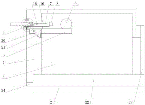
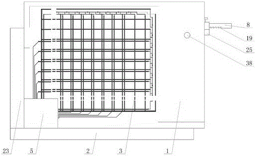
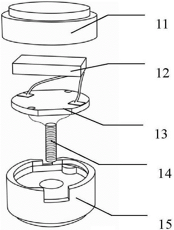
[0011] The electromagnetic positioning device of the present invention includes an induction positioning plate 4, a fixed plate 1 is installed on the outer edge of one side of the induction positioning plate 4, a support seat 7 is installed on the fixed plate 1 on the front of the induction positioning plate 4, and a track 6 is installed on the bottom of the support seat 7, Place projectile 9 on track 6, slide bar 8 is installed on support base 7, the first spring 18 is installed on slide bar 8, one end of slide bar 8 length direction is positioned at projectile 9 one side, and slide bar 8 other ends are positioned at fixed plate 1 Outside, the coil array circuit of horizontal and vertical arrangement is arranged on the back side of induction positioning plate 4, and USB interface is arranged on induction positioning plate 4, and USB interface is connected with computer by line, and throwing body 9 has upper casing 11 and lower casing 15, and upper The casing 11 and the lower c...


PUM


Abstract

The invention provides an electromagnetic positioning device, which comprises an induction positioning plate. The outer boundary of a side of the induction positioning plate is equipped with a fixing plate. A support base is mounted on the fixed plate on the front of the induction positioning plate. The lower portion of the support base is equipped with a track on which a projectile is disposed. A slide rod is mounted on the support base. A first spring is mounted on the slide rod. One end of the slide rod in the length direction is located at one side of the projectile, while the other end of the slide rod is located at the outer side of the fixing plate. The back of the induction positioning plate is provided with horizontally and vertically arranged coil array circuits. A USB interface is disposed in the induction positioning plate and is connected with a computer through a line. The projectile has an upper shell and a lower shell, and forms a cavity once being closed. A battery is mounted in the cavity and is connected with a circuit board via a wire. The circuit board is connected with a magnetic core coil via the wire. The invention can display the horizontal projectile motion as the resultant motion of the uniform linear motion in a horizontal direction and the free-fall motion in a vertical direction via the computer, and has the advantages of easy operation, low maintenance rate and long service life.

Description

technical field [0001] The invention relates to a teaching tool, which is an electromagnetic positioning device. Background technique [0002] In middle school physics teaching, it is necessary to describe the two-dimensional motion trajectory for flat throwing motion, oblique throwing motion, motion synthesis, etc., and the intuitive teaching needs to be completed by experiment. The existing experimental teaching of moving objects in a two-dimensional plane has many structures. The traditional experiments are divided into: stroboscopic photography and electric spark tracing. These two methods are still used in many schools at present. The shortcomings of these methods are obvious, the measurement method is indirect, the experimental equipment is difficult to operate, and the coordinate value of the projectile position cannot be directly read, and personnel are required to draw and describe points; the success rate of one-time experiments is not high, and multiple operations...

Claims


Application Information

Patent Timeline
Patent Type & Authority Applications(China)
IPC IPC(8): G09B23/10
CPCG09B23/10
Inventor 冯容士李鼎赵进
Owner SHANDONG YUANDA LLONGWILL EDUCATIONAL SCI & TECH LTD
Why Eureka
Try Eureka