Dynamic and variable time constant filter and filtering method

A technology of time constant and filter, applied in the direction of digital technology network, impedance network, electrical components, etc., can solve the problems of slow encoder output response speed, difficult and sensitive selection of output filter time constant, and influence on response speed, etc.

Active Publication Date: 2016-08-10
贵州极芯科技有限公司
View PDF3 Cites 2 Cited by
  • Summary
  • Abstract
  • Description
  • Claims
  • Application Information

AI Technical Summary

Problems solved by technology

However, the reference of the filter will slow down the output response speed of the encoder, and in a high-speed motion system, the control accuracy will decrease.
[0008] Therefore, the time constant selection of the output filter becomes very difficult and sensitive
If the time constant is too small, noise cannot be filtered out; if the time constant is too large, it will affect the response speed

Method used


Image

  • Dynamic and variable time constant filter and filtering method
  • Dynamic and variable time constant filter and filtering method
  • Dynamic and variable time constant filter and filtering method

Examples


Embodiment 1

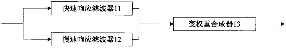
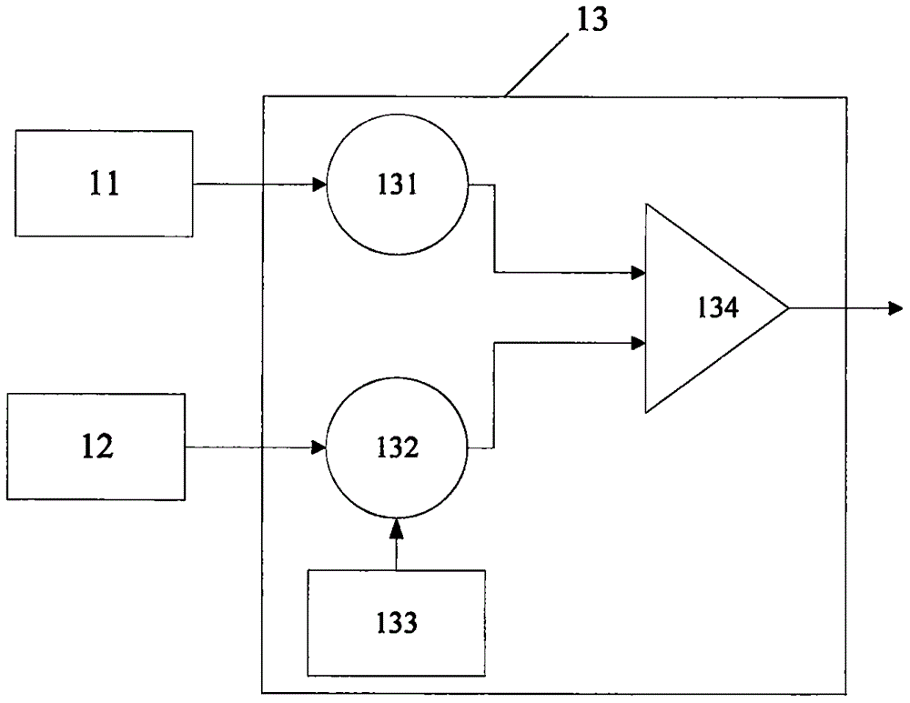
[0033] Embodiment 1, the dynamic variable time constant filter of the present embodiment, see figure 1 As shown, it includes: a fast response filter 11 and a slow response filter 12, and a variable weight synthesizer 13 connected to both the fast response filter 11 and the slow response filter 12. The input signal is simultaneously input to the fast response filter 11 and the slow response filter 12 to be processed separately, and then input into the variable weight synthesizer 13 in two ways. By adjusting the weight coefficient, the purpose of changing the response speed of the filter can be achieved, and then synthesized by variable weight The device synthesizes the two input signals and outputs the signal.

[0034] In specific implementation, the fast response filter 11 and the slow response filter 12 are digital low-pass filters with different time constants respectively, and the time constants of the fast response filter 11 and the slow response filter 12 can be selected ...

Embodiment 2

[0037] Embodiment 2, the filtering method of the dynamic variable time constant of the present embodiment, see Figure 4 shown, including the following main steps:

[0038] S21. Simultaneously input the input signal to the fast response filter and the slow response filter for processing respectively.

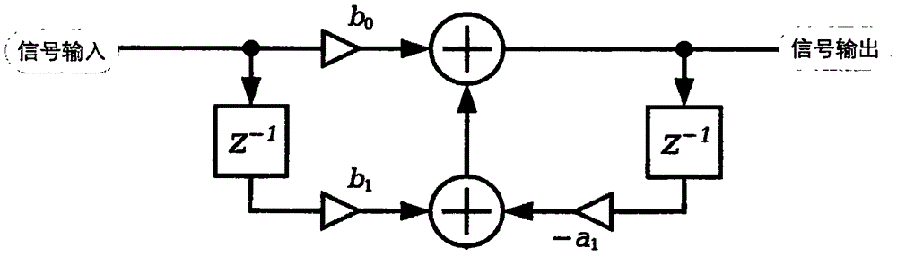
[0039]More specifically, the fast-response filter and the slow-response filter receive input signals at the same time and maintain a continuous working state. The fast-response filter and the slow-response filter are digital low-pass filters with different time constants, including but not limited to Butterworth filters, Chebyshev filters or elliptic filters. The fast-response filter can use a first-order filter, a second-order filter, or a high-order filter, and the slow-response filter can also use a first-order filter, a second-order filter, or a high-order filter. In this embodiment, a digital first-order low-pass filter is taken as an example, such as Figure 5 A schemat...


PUM


Abstract

The invention provides a dynamic and variable time constant filter and a filtering method, belonging to the technical field of electronic circuits and aiming to compromise the contradiction between rapid response and low noise in the choosing of time constant of a filter. The filter comprises a rapidly responding filter and a slowly responding filter as well as a weight changeable synthesizer in connection with both the rapidly responding filter and the slowly responding filter. The method is performed as follows. Inputting signals are inputted simultaneously into the rapidly responding filter and the slowly responding filter where they will be processed respectively. The outputted signals from the rapidly responding filter and the slowly responding filter are then inputted simultaneously into the weight changeable synthesizer. The weight changeable synthesizer divides the outputted signals from the rapidly responding filter and the slowly responding filter by corresponding weight coefficients and then synthesizes and outputs them. According to the invention, the signals with weight coefficients can effectively control the responding time constant of a filter, and during the adjustment process of the time constant, the outputting remains stable, free from sudden fluctuations.

Description

【Technical field】 [0001] The invention relates to the field of electronic circuits, in particular to a dynamic variable time constant filter and a filtering method. 【Background technique】 [0002] At present, the encoder is widely used in servo motors, intelligent robots, CNC machine tools and other fields. It is a precision measuring device that converts angular displacement or linear displacement into electrical signals. The former is called a code disc, and the latter is called a yardstick. According to the readout method, the encoder can be divided into two types: contact type and non-contact type; according to the working principle, the encoder can be divided into two types: incremental type and absolute type. The incremental encoder converts the displacement into a periodic electrical signal, and then converts the electrical signal into a counting pulse, and uses the number of pulses to represent the magnitude of the displacement. Each position of the absolute encoder...

Claims


Application Information

Patent Timeline
Patent Type & Authority Applications(China)
IPC IPC(8): H03H17/00
Inventor 吕悦川钱炜宋海峰
Owner 贵州极芯科技有限公司
Why Eureka
Try Eureka