Dimming LED constant current driving system based on transistor oscillating circuit

A technology of oscillating circuit and constant current output, which is applied in the electronic field, can solve problems such as unable to output stable current, achieve good linearity, stable output current, and improve stability

Inactive Publication Date: 2016-08-10
CHENGDU BAIMIAO NETWORK TECH CO LTD
View PDF0 Cites 12 Cited by
  • Summary
  • Abstract
  • Description
  • Claims
  • Application Information

AI Technical Summary

Problems solved by technology

[0003] The purpose of the present invention is to overcome the defect that the traditional LED driving system is easily affected by external factors, resulting in its inability to output stable current, and to provide a dimming type LED constant current output driving system based on a transistor oscillator circuit

Method used


Image

  • Dimming LED constant current driving system based on transistor oscillating circuit
  • Dimming LED constant current driving system based on transistor oscillating circuit
  • Dimming LED constant current driving system based on transistor oscillating circuit

Examples


Embodiment

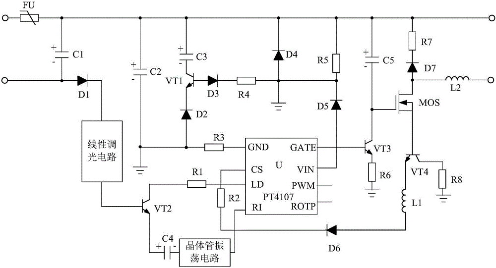
[0021] Such as figure 1 As shown, the dimming type LED constant current output driving system based on the transistor oscillating circuit of the present invention is mainly composed of a processing chip U, a transistor VT2, a resistor R1, a capacitor C4, a protection circuit, a transistor oscillating circuit, a linear dimming circuit, a low-pass Filter circuit, gate drive circuit and current feedback circuit.

[0022] Wherein, the low-pass filter circuit is serially connected between the protection circuit and the processing chip U. The linear dimming circuit is connected in series between the protection circuit and the base of the triode VT2. The resistor R1 is connected in series between the collector of VT2 and the LD pin of the processing chip U. The transistor oscillating circuit is connected in series between the negative electrode of the capacitor C4 and the RI pin of the processing chip U. The gate drive circuit is respectively connected to the GATE pin of the proce...


PUM


Abstract

The invention discloses a dimming LED constant current driving system based on a transistor oscillating circuit. The system is characterized in mainly comprising a processing chip U; a triode VT2; a capacitor C4; a protection circuit; a lowpass filtering circuit connected between the protection circuit and the processing unit U in series; a linear dimming circuit connected between the protection circuit and the base of the triode VT2 in series; a resistor R1 connected between the collector of the triode VT2 and the LD pin of the processing chip U in series; and the transistor oscillating circuit connected between the cathode of the capacitor C4 and the RI pin of the processing chip U in series. The anode of the capacitor C4 is connected with the emitter of the triode VT2. According to the system, the brightness of the LED can be adjusted according to demands. Compared with the traditional LED driving system, the system has the advantages that the linearity when the brightness of the LED is adjusted is high, the LED can work more stably, and the twinkling phenomenon is avoided.

Description

technical field [0001] The invention relates to the field of electronics, in particular to a dimming type LED constant current output driving system based on a transistor oscillator circuit. Background technique [0002] At present, due to the characteristics of low energy consumption, long service life, safety and environmental protection, LED lamps have become one of the mainstream products for people's living lighting. With the popularity of LEDs and the continuous improvement of people's requirements for lighting effects, new challenges have been brought to LED drive systems. However, the traditional LED drive system is easily affected by interference factors, which makes it unable to output a stable current, which affects the normal operation of the LED to a large extent, and even damages the LED in severe cases. Contents of the invention [0003] The purpose of the present invention is to overcome the defect that the traditional LED driving system is easily affected...

Claims


Application Information

Patent Timeline
Patent Type & Authority Applications(China)
IPC IPC(8): H05B33/08H05B44/00
CPCH05B45/395H05B45/10Y02B20/30
Inventor 刘磊
Owner CHENGDU BAIMIAO NETWORK TECH CO LTD
Why Eureka
Try Eureka