Supercharge Your Innovation With Domain-Expert AI Agents!

Ball nut assembly for an electromechanically actuable parking brake assembly of a brake assembly

A ball nut and brake assembly technology, which is applied to brake actuators, brake action starting devices, brakes, etc., can solve problems such as limited packaging space

Inactive Publication Date: 2016-08-10
KELSEY HAYES CO
View PDF5 Cites 0 Cited by
  • Summary
  • Abstract
  • Description
  • Claims
  • Application Information

AI Technical Summary

Problems solved by technology

However, the available packaging space for ball nut assemblies is limited in order to maximize vehicle occupant space

Method used


Image

  • Ball nut assembly for an electromechanically actuable parking brake assembly of a brake assembly
  • Ball nut assembly for an electromechanically actuable parking brake assembly of a brake assembly
  • Ball nut assembly for an electromechanically actuable parking brake assembly of a brake assembly

Examples


Embodiment Construction

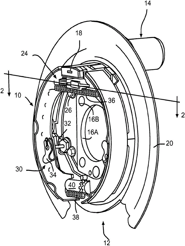
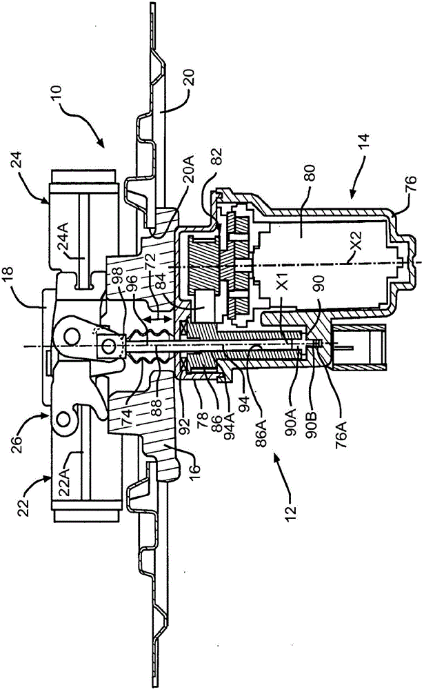
[0037] Referring now to FIGS. 1 and 2 , there is shown a prior art drum-in-disc parking and emergency brake 10 of a vehicle-drum-in-disc disc brake assembly, generally indicated at 12 . The actuating assembly has an electric actuator unit (generally indicated at 14) for actuating its drum-in-disc parking and emergency brake 10 (ie: parking brake). The general structure and operation of brake assembly 12 is conventional in the art, and may be generally similar to those described in U.S. Patent No. 5,322,145 to Evans, U.S. Patent No. 6,729,444 to Schmandt et al., and U.S. Patent No. 6,729,444 to Boyle et al. No. 8,011,482 of the type shown and described, the disclosures of which are hereby incorporated by reference in their entirety. While the present invention will describe and illustrate the particular brake assembly 12 disclosed herein, it will be understood that the present invention may be used with other drum-in-disc brake assemblies in relation to the parking and emergenc...


PUM


Abstract

A brake assembly includes a service brake assembly and an electromechanically actuable parking brake assembly. The electromechanically actuable parking brake assembly has a ball nut assembly comprising a ball screw and a ball nut. The ball screw and ball nut form a raceway for bearing members. The bearing members circulate within an internal path formed in the ball screw.

Description

[0001] related application [0002] This patent application claims priority to and all benefit of co-pending U.S. Provisional Patent Application Serial No. 61 / 909472, filed November 27, 2013, and entitled "For Disc Brake Assemblies Ball Nut Assembly for an Electromechanically Actuated Parking Brake Assembly". technical field [0003] The present invention relates generally to vehicle brake assemblies and, in particular, to an improved structure for a ball nut assembly for an electromechanically actuatable parking brake assembly of a brake assembly. Background technique [0004] Most vehicles are equipped with a braking system for slowing or stopping the movement of the vehicle in a controlled manner. A typical braking system for a motor vehicle or light truck includes a disc brake assembly for each front wheel and a drum or disc brake assembly for each rear wheel. The brake assemblies are actuated by hydraulic or pneumatic pressure generated when the operator of the vehicl...

Claims


Application Information

Patent Timeline
Patent Type & Authority Applications(China)
IPC IPC(8): B60T7/10F16H25/20
CPCF16D65/18B60T7/107F16D51/20F16D55/224F16D65/22F16D2121/14F16D2121/24F16D2125/36F16D2125/48F16H25/2228
Inventor K·E·格伯M·巴尔博萨C·吴
Owner KELSEY HAYES CO
Features
  • R&D
  • Intellectual Property
  • Life Sciences
  • Materials
  • Tech Scout
  • Unparalleled Data Quality
  • Higher Quality Content
  • 60% Fewer Hallucinations
Learn More