Electronic charge injection circuit for radiation detector

A technology of radiation detectors and electronic circuits, which is applied in radiation measurement, radiation intensity measurement, X/γ/cosmic radiation measurement, etc., and can solve problems such as complex calibration

Active Publication Date: 2016-08-10
原子能和辅助替代能源委员会 +1
View PDF7 Cites 2 Cited by
  • Summary
  • Abstract
  • Description
  • Claims
  • Application Information

AI Technical Summary

Problems solved by technology

Correcting for these changes requires complex equipment

Method used


Image

  • Electronic charge injection circuit for radiation detector
  • Electronic charge injection circuit for radiation detector
  • Electronic charge injection circuit for radiation detector

Examples


Embodiment Construction

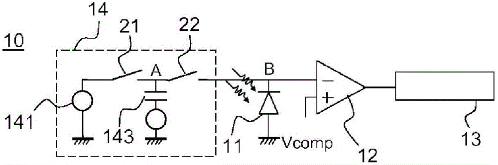
[0036] figure 1 A circuit diagram representing the electronic circuit of a pixel 10 in a matrix radiation detector according to the prior art (eg described in patent application FR2977413). Each pixel 10 forms a photosensitive spot of the matrix detector. The electronic circuit comprises a radiation sensitive element 11 and a comparator 12 with a switching potential V comp_bascul , whose first input receives the threshold potential V comp , and the second input is used to connect to the integration node B, which is linked to the cathode of the sensitive element 11 .

[0037]Sensitive element 11 has stray capacitance. Charges generated by the sensitive element 11 when receiving radiation can be stored by the stray capacitance of the sensitive element 11 . The collected charge causes a change in the potential on integrating node B, referred to as the integrating potential. Sensitive element 11 may be a photodiode or phototransistor, or more generally any photosensitive elem...


PUM


Abstract

The invention relates to an electronic read circuit for a radiation detector comprising: an element (11) sensitive to the radiation, an injection circuit, able to inject a charge at one terminal of the sensitive element (11), the injection circuit (14) extending between at least one input terminal and one output terminal, the output terminal being able to be connected to said sensitive element (11), the injection circuit (14) being able to produce a charge under the effect of a trigger pulse. The injection circuit is able to inject a first charge when an input terminal is connected to a first input potential and a second charge when an input terminal is connected to a second input potential (Vinj2, Phiinj)). The circuit comprises means for storing a difference between an output potential of the injection circuit (14), called equilibrium potential, and a reference potential, such that the second charge depends on the second input potential and on said equilibrium potential.

Description

technical field [0001] The invention relates to an electronic circuit for a radiation detector adapted to quantify the radiation of photons received by a counter-charge injection circuit. The invention relates in particular to a matrix radiation detector for X- or gamma-ray radiation imaging comprising a matrix of CMOS technology pixels associated with a structure for converting X- or gamma-rays into electrical charges. Background technique [0002] A matrix radiation detector comprises a matrix of pixels and electronic circuitry forming a readout module. Each pixel includes a photosensitive element that generates a charge proportional to the amount of photons received. These charges, also called photocharges, are processed by the readout module in order to supply an item of information representing the amount of photons received by each photosensitive element. Using CMOS technology enables the integration of a readout module in each pixel. Thus, the charge can be convert...

Claims


Application Information

Patent Timeline
Patent Type & Authority Applications(China)
IPC IPC(8): G01T1/16
CPCG01T1/24G01T1/20184H03K4/023H04N25/59H04N25/76
Inventor A·哈比卜M·阿克斯
Owner 原子能和辅助替代能源委员会
Why Eureka
Try Eureka