
Patsnap Eureka
For R&D, Patsnap Eureka makes reading and utilizing patents & technical documents easy.
Patsnap Eureka AIR
Designed for self-driven R&D workflows. Generate viable solutions, solve complex R&D challenges, empower your innovation with AI.

Patsnap Eureka Materials
Designed for material experts only. Revolutionize your material R&D, from search, analyze, to developing new materials.

TechResearch
Generate reliable direction feasibility study reports for your R&D in just a few steps.

TechSeek
Discover and master advanced knowledge NOW. Basics, ideas, possibilities, all at once.

TechMind
As an expert in R&D Theories, TechMind can generates customized viable solutions instantly.

TechRisk
Analyze your overall solution with one click, know your potential R&D risks in advance.

TechMonitor
Get weekly tech updates, stay abreast of the latest tech innovations and key insights.
Input device
A technology of input device and input unit, which is applied in the direction of transportation and packaging, input/output process of data processing, input/output of user/computer interaction, etc., and can solve problems such as increased usage
- Summary
- Abstract
- Description
- Claims
- Application Information
AI Technical Summary
Problems solved by technology
Method used
Image

Examples
no. 1 approach
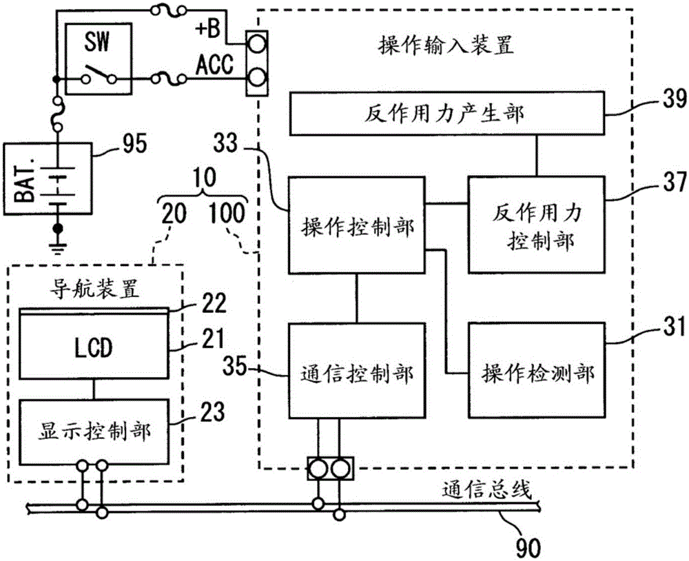
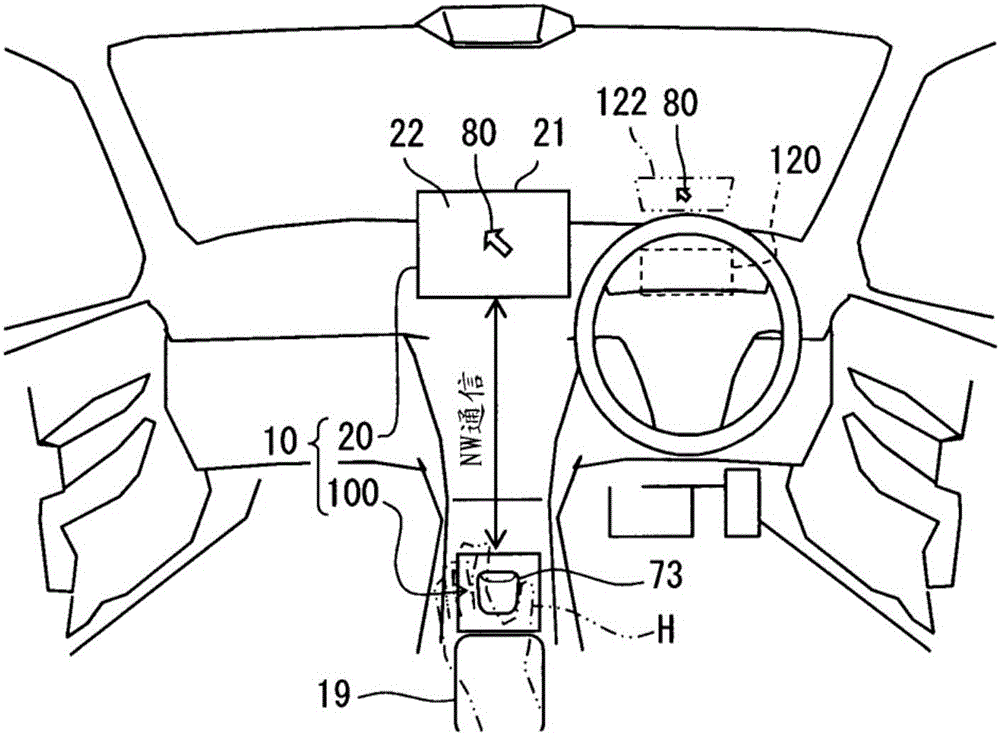
[0028] figure 1 The shown operation input device 100 according to the first embodiment of the present invention is mounted on a vehicle, and is connected to a display in the vehicle compartment, such as a navigation device 20 or a head-up display device (headup display) 120 (see figure 2 ) and the like together constitute the display system 10. Operation input device 100 such as figure 2 As shown, it is provided at a position adjacent to the palm rest 19 in the center console of the vehicle, so that the operation knob 73 is exposed in a range where the operator's hand can easily reach. When an operation force is input by the operator's hand H or the like, the operation knob 73 is displaced in the direction of the input operation force.
[0029] The navigation device 20 is installed in the dashboard of the vehicle, and the display screen 22 is exposed toward the driver's seat. Displayed on the display screen 22 are a plurality of icons associated with predetermined functio...
no. 2 approach
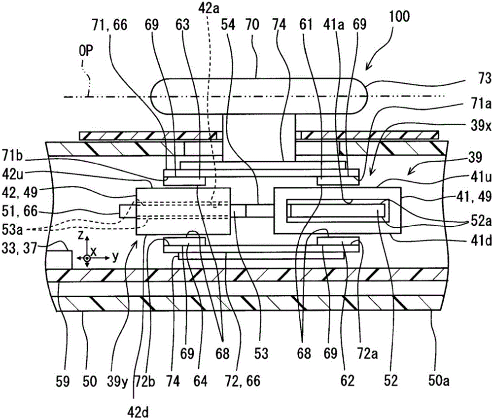
[0065] Figure 9 ~ Figure 13 The illustrated second embodiment of the invention is a modification of the first embodiment. The reaction force generator 239 of the operation input device 200 of the second embodiment is composed of a first VCM 239x and a second VCM 239y, a magnetic circuit forming body 266 including a movable yoke 251 and two fixed yokes 271 and 272 , and the like. The first VCM 239x has a first coil 241 and two magnets 261 , 262 . The second VCM 239y has a second coil 242 and two magnets 263 , 264 .
[0066] Figure 9 ~ Figure 11 The coils 241 and 242 shown correspond to the coils 41 and 42 of the first embodiment (see image 3 )Structure. The respective coils 241 and 242 form storage chambers 241a and 242a, upper coil side surfaces 241u and 242u, and lower coil side surfaces 241d and 242d, respectively, as in the first embodiment. Each magnet 261-264 and the movable yoke part 251 are accommodated in each storage chamber 241a, 242a. The respective upper c...
no. 3 approach
[0078] Figure 14 , Figure 15 The illustrated third embodiment of the present invention is another modified example of the first embodiment. In the reaction force generation unit 339 of the operation input device 300 of the third embodiment, the first coil 41 and the second coil 42 can move together with the movable unit 70 . The reaction force generation part 339 is comprised from the 1st VCM39x, the 2nd VCM39y, and the magnetic circuit forming body 366 which includes the movable yoke part 351 and the two fixed yoke parts 371 and 372, etc.
[0079] The movable yoke 351 is the same as the movable yoke 251 of the second embodiment (see Figure 9 ) are similarly suspended by the knob base 74 in a state separated from the respective coils 41, 42 and the respective fixed yoke portions 371, 372. The movable yoke portion 351 is provided with a first coil side yoke portion 352 , a second coil side yoke portion 353 , and a connection portion 354 . The coil side yokes 352 and 353 ...
PUM
 Abstract
Description
Claims
Application Information
 - R&D Engineer
- R&D Manager
- IP Professional
- Industry Leading Data Capabilities
- Powerful AI technology
- Patent DNA Extraction
Browse by: Latest US Patents, China's latest patents, Technical Efficacy Thesaurus, Application Domain, Technology Topic, Popular Technical Reports.
© 2024 PatSnap. All rights reserved.Legal|Privacy policy|Modern Slavery Act Transparency Statement|Sitemap|About US| Contact US: help@patsnap.com