Check patentability & draft patents in minutes with Patsnap Eureka AI!

Control method for electrical converter with LC filter

An electrical converter and filter technology, applied in electronic commutation motor control, direct torque control, motor generator control, etc., can solve problems such as higher-order resonance amplification, difficulty in ensuring closed-loop system stability, system oscillation, etc.

Active Publication Date: 2016-08-10
ABB (SCHWEIZ) AG
View PDF4 Cites 5 Cited by
  • Summary
  • Abstract
  • Description
  • Claims
  • Application Information

AI Technical Summary

Problems solved by technology

[0005] From a control point of view, only LC filters may be difficult to ensure the stability of closed-loop systems (converter, attached cables, transformers, motors, etc.)
Due to the resonant peak of the LC filter, higher order resonances in the system may be amplified and the system may oscillate

Method used


Image

  • Control method for electrical converter with LC filter
  • Control method for electrical converter with LC filter
  • Control method for electrical converter with LC filter

Examples


Embodiment Construction

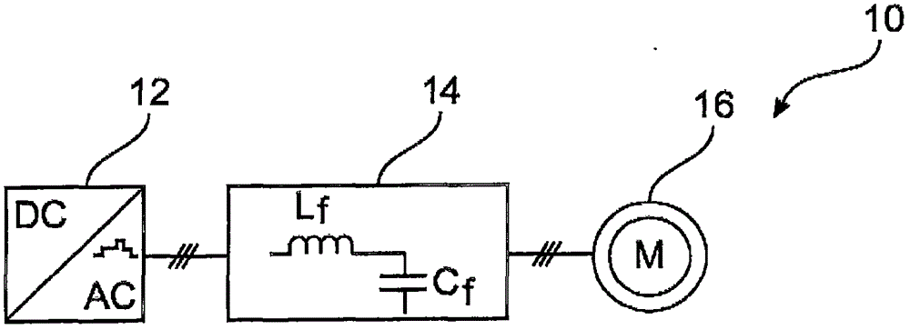
[0067] figure 1 A converter system 10 is shown having an inverter (DC to AC converter) 12 connected on the output side via an LC filter 14 to a rotating electrical machine 16, eg a generator or an electric motor. As shown, the converter 12 may have a three-phase output. However, the converter system 10 may also be a single-phase system.

[0068] The inverter 12 produces an N-level output voltage, which is smoothed by an LC filter 14 that includes a filter inductor L connected between the converter 12 and the rotating electrical machine 16 f . Filter capacitor C f In parallel with the converter 12 and / or the rotating electrical machine 16 . It should be understood that in a polyphase system, the filter inductor L f and filter capacitor C f (and the components described below) include a number of physical inductances and capacitances corresponding to the number of phases.

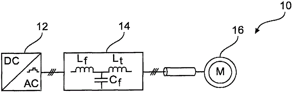
[0069] figure 2 Another converter system 10 is shown with additionally a long cable 18 between th...


PUM


Abstract

An electrical converter (12) is interconnected via a filter (14) with an electrical load (16) or an electrical power source (20). A method for controlling the converter (12) comprises the steps of: receiving a reference flux (psi *i) for the electrical converter (12); determining output signals (y) comprising currents and / or voltages measured in the filter (14); determining an estimated flux (psi i) from the output signals (y); determining a corrective flux (psi i,damp) from the output signals (y) based on a mathematical model of the filter (14) and a quadratic cost function; determining control input signals (u) for the electrical converter (12) based on a sum of the estimated flux (psi i) and the corrective flux (psi i,damp); controlling the converter (12) with the control input signals (u); and algorithmic filtering of at least one of the output signals (y) by applying a signal filter (32) to the at least one output signal, which is designed for amplifying the at least one output signal at a resonance frequency (40) of the filter (14), whereby the corrective flux (psi i,damp) is determined from the filtered output signals.

Description

technical field [0001] The invention relates to a method for controlling an electrical converter and a converter system. Background technique [0002] Electrical converters, such as active rectifiers and inverters, are used to convert a first electrical current into a second electrical current having a different frequency, eg to power a load, to connect a power supply to a grid or to interconnect two electrical networks. [0003] Specific medium voltage converters are linked with low pass input or output filters which are passively attenuated by large resistors. Typically, the filter includes a filter inductor and a filter capacitor connected in series with a damping resistor. Such filters are called LCR filters. However, such a structure may have considerable power loss in the resistor and may not provide a proper current curve at the output due to the slow decay rate of its damping capability at higher frequencies. [0004] Since the converter needs to have a certain ma...

Claims


Application Information

Patent Timeline
Patent Type & Authority Applications(China)
IPC IPC(8): H02M1/12H02P21/00H02P21/14H02P23/00H02P23/14
CPCH02P21/141H02P23/14H02P21/30H02P23/30H02M7/53875H02M1/126G05B2219/41406H02M7/53873H02M1/0003
Inventor P·阿-霍卡耶姆T·格耶N·奥伊科诺莫
Owner ABB (SCHWEIZ) AG
Features
  • R&D
  • Intellectual Property
  • Life Sciences
  • Materials
  • Tech Scout
  • Unparalleled Data Quality
  • Higher Quality Content
  • 60% Fewer Hallucinations
Learn More