Orthodontic bracket system and tooth orthodontic method

A technology of orthodontic brackets and brackets, which is applied in the field of orthodontics, traction/locking components, can solve the problems of small operating space, small force on the traction hook, narrow field of view, etc., to achieve convenient installation and disassembly, and reduce discomfort The effect of sense and convenient operation

Active Publication Date: 2020-06-09
吉利
View PDF9 Cites 0 Cited by
  • Summary
  • Abstract
  • Description
  • Claims
  • Application Information

AI Technical Summary

Problems solved by technology

[0004] The traction hook is integrally welded on the bracket body. The traction hook cannot be disassembled. Because it protrudes from the surface of the bracket body, the traction hook is placed in the patient's mouth along with the bracket body during the whole correction. Bring obvious discomfort, the movement of the lips will cause the oral mucosa and the buccal surface of the teeth to rub against the traction hook, which is easy to damage the oral mucosa and the buccal surface of the teeth
[0005] Another method is to temporarily insert the traction wire into the bracket body and bend it when traction is required, which will shorten the time the traction hook remains in the oral cavity and reduce the discomfort of the oral cavity; Temporary bending is required. Due to the need to operate the bracket body fixed on the tooth surface, the operating space is small, the field of vision is narrow, and installation and disassembly are very inconvenient, which also affects the effect of traction, so that the force of the traction hook is small and cannot Meeting the needs of orthodontics

Method used


Image

  • Orthodontic bracket system and tooth orthodontic method
  • Orthodontic bracket system and tooth orthodontic method
  • Orthodontic bracket system and tooth orthodontic method

Examples


Embodiment 1

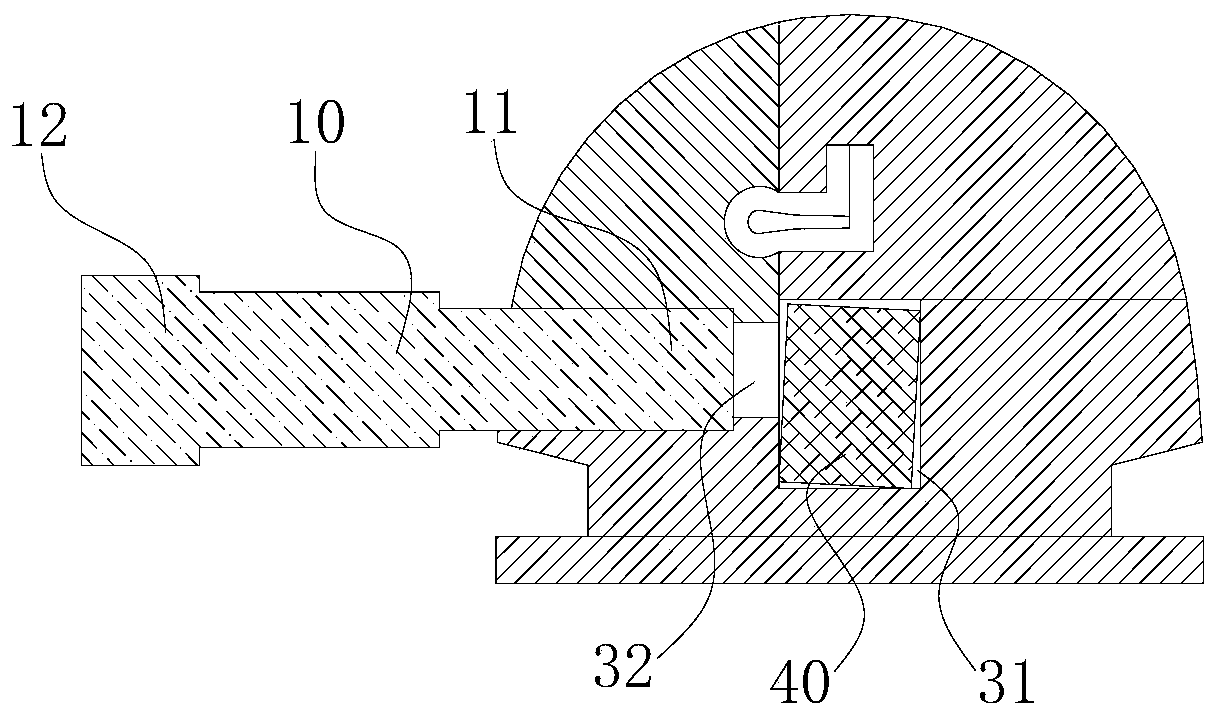
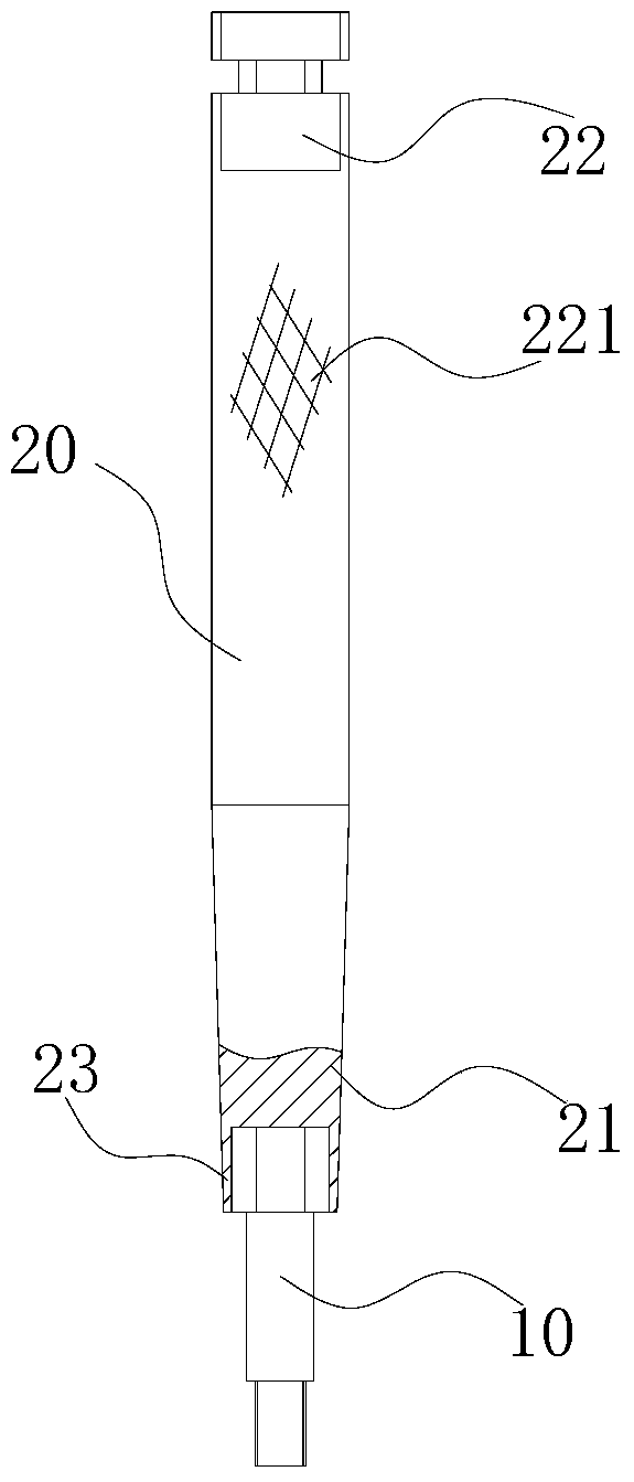
[0063] Such as Figure 1 to Figure 9 As shown, the orthodontic bracket system includes a bracket body 30 and a traction element. The traction element includes a strip-shaped nail body 10 and a handle 20. The front end of the nail body 10 is the first fixed end 11, and the rear end is the first fixed end. The screwing end 12 and the first fixed end 11 are provided with a connecting external thread 111 , and a first force application surface 121 is provided at least at the end of the first screwing end 12 . A main groove 31 is provided on the bracket body 30 , and a reserved hole 32 is provided on the side of the bracket body 30 , the reserved hole 32 is a through hole, and its inner end is connected to the main groove 31 . The inner diameter of the reserved hole 32 is 0.2 to 1.6 millimeters (wherein, preferably 0.5 millimeters to 1.2 millimeters), and the inner wall of the reserved hole 32 is provided with a connecting internal thread; the cross-sectional area of ​​the nail bod...

Embodiment 2

[0088] Such as Figure 10 , Figure 11 As shown, in this embodiment, when the nail body 10 is in the maximum tightened state, the front end of the pressing section 122 protrudes from the main groove 31 .

[0089] Since the size of the archwire 40 will be smaller than the size of the main groove 31 (otherwise the archwire 40 cannot be placed in the main groove 31), the archwire 40 will deviate in the main groove 31, thereby affecting orthodontics In this embodiment, the size of the nail body 10 is slightly longer than that of Embodiment 1. At this time, the nail body 10 passes through the reserved hole 32 and presses against the arch wire 40, and the arch wire 40 is pressed through the nail body 10. 40 is locked. Compared with the first embodiment, this embodiment can reduce the deviation of the arch wire 40 and improve the accuracy of the arch wire 40 for tooth correction.


PUM


Abstract

The invention discloses a traction / locking element, a traction / locking set, an orthodontic bracket, an orthodontic bracket system and a tooth orthodontic method. The traction / locking element includes a strip-shaped nail body. The cross-sectional area of ​​the nail body is 0.06 to 2.5 square millimeters, and the length is 0.8 to 4.5 millimeters. The front end of the nail body is the first fixed end, the rear end is the first screwing end, and the first fixed end is provided with a connecting external thread. The outer diameter of the connecting external thread is 0.2 to 1.6 millimeters, and a first force-applying surface is provided at least at the end of the first screwing end. The purpose of the present invention is to overcome the defects of the prior art. The present invention can timely perform traction according to the traction timing of orthodontics to reduce the discomfort in the oral cavity; it is very convenient to install and disassemble, and the traction to the teeth is very reliable.

Description

technical field [0001] The invention belongs to the field of orthodontics, and in particular relates to a traction / locking element, a traction / locking set, an orthodontic bracket, an orthodontic bracket system and a tooth orthodontic method. Background technique [0002] Brackets are an important part of fixed orthodontic technology. They are appliances used to correct tooth alignment deformities. They are directly fixed on the surface of the crown. [0003] In the process of orthodontics, in order to move the teeth, it is necessary to move the teeth to be corrected to the designed direction through the traction parts to achieve the effect of traction. , there are mainly two existing approaches: [0004] The traction hook is integrally welded on the bracket body. The traction hook cannot be disassembled. Because it protrudes from the surface of the bracket body, the traction hook is placed in the patient's mouth along with the bracket body during the whole correction. It b...

Claims


Application Information

Patent Timeline
Patent Type & Authority Patents(China)
IPC IPC(8): A61C7/02A61C7/34
CPCA61C7/02A61C7/023A61C7/34A61C7/22A61C7/14
Inventor 吉利
Owner 吉利
Why Eureka
Try Eureka