Noncircular part deburring robot based on force compensation

A deburring and robot technology, applied in the direction of machine tools, grinding racks, grinding workpiece supports, etc. suitable for grinding workpiece edges, can solve the problem of no cutting force, achieve uniform deburring cutting, and ensure deburring quality , to avoid the effect of not reflecting

Active Publication Date: 2016-08-17
ZHENJIANG DALI HYDRAULIC MOTOR
View PDF7 Cites 8 Cited by
  • Summary
  • Abstract
  • Description
  • Claims
  • Application Information

AI Technical Summary

Problems solved by technology

For example, the Chinese patent literature with the publication number CN103084947A describes a machine tool for deburring the outer circle of shaft parts, which can simultaneously remove the burrs at the ring grooves, straight grooves and inclined grooves of multiple processed parts; another example, the publication number is The Chinese patent literature of CN103029017A discloses a robot deburring machine, including a feeding raceway, a deburring device, a robot, a manipulator clamping device, a feeding raceway, a body, a bracket and protection, which can realize the surface and inner holes of automobile engine parts. Large batches of flexible deburring, these technical solutions have no cutting force control, and are not suitable for uniform deburring and blunt processing of non-circular parts such as cycloidal hydraulic motor housings

Method used


Image

  • Noncircular part deburring robot based on force compensation
  • Noncircular part deburring robot based on force compensation
  • Noncircular part deburring robot based on force compensation

Examples


Embodiment Construction

[0021] The embodiments of the present invention are described in detail below. This embodiment is implemented on the premise of the technical solution of the present invention, and detailed implementation methods and specific operating procedures are provided, but the protection scope of the present invention is not limited to the following implementation example.

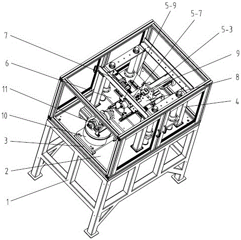
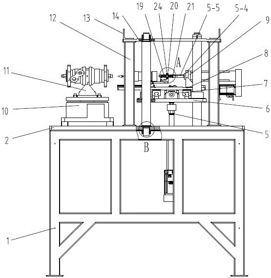
[0022] The basic composition of the non-circular part deburring robot based on force compensation of the present invention can be found in figure 1 , figure 2 , the base plate 2 in the middle of the frame 1 is equipped with four guide columns through the fixed guide frame 4, and the base plate 2 of the frame 1 is also equipped with a symmetrical tooling 11 located on the side of the fixed guide frame 4 as a workpiece clamping tool, and a Y-axis The vertically moving mounting plate 6 driven by the servo motion device 5, the guide column passes through the vertically moving mounting plate 6, and forms a vertically ...


PUM


Abstract

The invention relates to a noncircular part deburring robot based on force compensation, belonging to the technical field of hydraulic transmission detection. The robot comprises a rack, a workpiece clamping tool and a control circuit, wherein a vertical moving mounting plate is mounted on the rack; a guide upright and the vertical moving mounting plate form a vertical moving pair; a horizontal moving mounting plate is mounted on the vertical moving mounting plate; a track control output end of the control circuit is connected with the controlled ends of Y-axis and X-axis servo motion devices respectively; a telescopic grinding head and a compensation shaft motion device are mounted on the horizontal moving mounting plate; the stretching/retraction direction of the grinding head faces the workpiece clamping tool and is vertical to the moving direction of the horizontal moving mounting plate; the compensation shaft motion device comprises a servo electric cylinder; a stretching end of the servo electric cylinder is coaxial with a spring guide rod; a front spring and a back spring are mounted on the two sides of a mounting seat respectively; a pre-tightening member is arranged at the front end of the front spring; the back spring is connected with the stretching end of the servo electric cylinder; and a signal output end of the tension/pressure sensor is connected with the controlled end of the servo electric cylinder through the control circuit.

Description

technical field [0001] The invention relates to an automatic deburring device, in particular to a non-circular part deburring robot based on force compensation, which belongs to the technical field of mechanical processing. Background technique [0002] Burrs and protrusions on mechanical parts not only cause shape errors and affect the surface quality of parts, but also bring troubles to the subsequent processing and assembly of parts. Therefore, removing burrs in time is an important process in the mechanical manufacturing process. [0003] For a long time, the deburring work of the cycloid hydraulic motor casing has been done manually. First, the workers move it from the small trolley where the cycloid hydraulic motor casing is stacked to the operating table, and then use a file on the cycloid hydraulic motor casing. Lightly file and deburr the contoured edges of the main flange face and port face before placing back on the transport cart. So far, the efficiency and qua...

Claims


Application Information

Patent Timeline
Patent Type & Authority Applications(China)
IPC IPC(8): B24B9/00B24B41/02B24B41/06
CPCB24B9/00B24B41/02B24B41/06
Inventor 施光林张智敏杨丽华周峰翁爱光王志生
Owner ZHENJIANG DALI HYDRAULIC MOTOR
Why Eureka
Try Eureka