Multi-rotor-wing unmanned aerial vehicle

A multi-rotor unmanned aerial vehicle and rotor technology, which is applied in the directions of rotorcraft, unmanned aerial vehicles, motor vehicles, etc., can solve the problems of danger and inconvenience of hand-held camera shooting, and achieve good tracking shooting, good use value, The effect of high wind resistance

Inactive Publication Date: 2016-08-17
安徽天鹰兄弟无人机科技创新有限公司
View PDF7 Cites 12 Cited by
  • Summary
  • Abstract
  • Description
  • Claims
  • Application Information

AI Technical Summary

Problems solved by technology

UAV + industry application is the real rigid demand of UAV. It is currently used in aerial photography, agriculture, plant protection, selfie, express transportation, disaster rescue, observation of wild animals, monitoring of infectious diseases, surveying and mapping, news reports, power inspection, disaster relief, Applications in the fields of film and television shooting, romantic manufacturing, etc. have greatly expanded the use of drones themselves. Developed countries are also actively expanding industry applications and developing drone technology. With the development of society, more and more people start As a sport of rafting, many people like to record the video of their movement through the camera when they are exercising, but it is often inconvenient to hold the camera to shoot while exercising, and if it is shot, it will often be dangerous, so A multi-rotor UAV is designed

Method used


Image

  • Multi-rotor-wing unmanned aerial vehicle
  • Multi-rotor-wing unmanned aerial vehicle

Examples


Embodiment

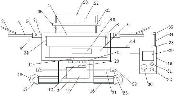
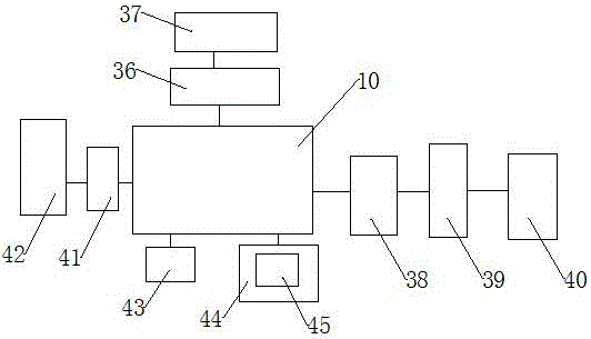
[0017] Example: see figure 1 and figure 2 , the present invention provides a technical solution: a multi-rotor UAV, including a frame 1, a landing gear 2 and a rotor 3, the landing gear 2 is arranged at the lower end of the frame 1, and a support plate 4 is arranged at the upper end of the frame 1 to support The plate 4 is connected with a rotor rod 5, and there are four rotor rods 5, the rotor rod 5 is provided with a rotor 3, the support plate 4 is provided with a positioning pin 6, and a rotating shaft 7 is provided between the support plate 4 and the frame 1. The frame 1 is provided with a battery box 8, the lower end of the battery box 8 is provided with a control box 9, the control box 9 is provided with a main control chip 10, the lower end of the control box 9 is provided with a swivel base 11, and the lower end of the swivel base 11 is connected with a wide-angle camera 12 The two ends of the wide-angle camera 12 are provided with an infrared signal receiver 13, the...


PUM


Abstract

The invention discloses a multi-rotor-wing unmanned aerial vehicle. The multi-rotor-wing unmanned aerial vehicle comprises a rack, an undercarriage and rotor wings, wherein the undercarriage is arranged at the lower end of the rack; a supporting plate is arranged at the upper end of the rack; the supporting plate is connected with rotor wing rods; the four rotor wing rods are arranged and the rotor wings are arranged on the rotor wing rods; positioning pins are arranged on the supporting plate; a rotary shaft is arranged between the supporting plate and the rack; the rack is internally provided with a battery box; a control box is arranged at the lower end of the battery box; a main control chip is arranged in the control box; a rotary seat is arranged at the lower end of the control box; a periscopic camera is connected with the lower end of the rotary seat; infrared signal receivers are arranged at the two ends of the periscopic camera; the control box is connected with a remote controller through an infrared signal; a buffering rubber sleeve is bound on the undercarriage; weight-increasing balls are arranged at the two ends of the undercarriage; sponge sleeves sleeve the outer sides of the weight-increasing balls; very good tracing and photographing can be realized; the plurality of rotor wings are arranged so that the flight of the unmanned aerial vehicle is more stable; the unmanned aerial vehicle has relatively high wind-resisting property and is worthy of being popularized.

Description

technical field [0001] The invention relates to the technical field of unmanned aerial vehicles, in particular to a multi-rotor unmanned aerial vehicle. Background technique [0002] According to the application field, UAV can be divided into military and civilian. In terms of military use, UAVs are divided into reconnaissance aircraft and target aircraft. UAV + industry application is the real rigid demand of UAV. It is currently used in aerial photography, agriculture, plant protection, selfie, express transportation, disaster rescue, observation of wild animals, monitoring of infectious diseases, surveying and mapping, news reports, power inspection, disaster relief, Applications in the fields of film and television shooting, romantic manufacturing, etc. have greatly expanded the use of drones themselves. Developed countries are also actively expanding industry applications and developing drone technology. With the development of society, more and more people start As a...

Claims


Application Information

Patent Timeline
Patent Type & Authority Applications(China)
IPC IPC(8): B64C27/08B64D1/18
CPCB64C27/08B64D1/18B64D2211/00B64U2101/00B64U50/19B64U2201/20B64U10/10
Inventor 不公告发明人
Owner 安徽天鹰兄弟无人机科技创新有限公司
Why Eureka
Try Eureka