Fiber drawing process

A wire drawing and process technology, applied in the field of optical fiber production, can solve the problems of unstable cooling effect of the shaping tube, untreated cooling water, and large waste, so as to reduce the defect rate of products, ensure the cooling effect, and increase the maintenance cycle.

Active Publication Date: 2018-06-26
HANGZHOU FUTONG COMM TECH CO LTD
View PDF4 Cites 0 Cited by
  • Summary
  • Abstract
  • Description
  • Claims
  • Application Information

AI Technical Summary

Problems solved by technology

[0004] The present invention provides an optical fiber drawing process, which solves the defects of untreated cooling water, large waste, and unstable cooling effect of the shaping tube in the existing optical fiber drawing process.

Method used


Image

  • Fiber drawing process
  • Fiber drawing process
  • Fiber drawing process

Examples


Embodiment

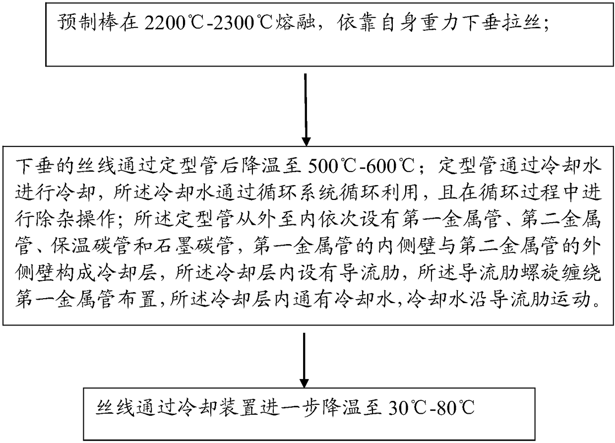
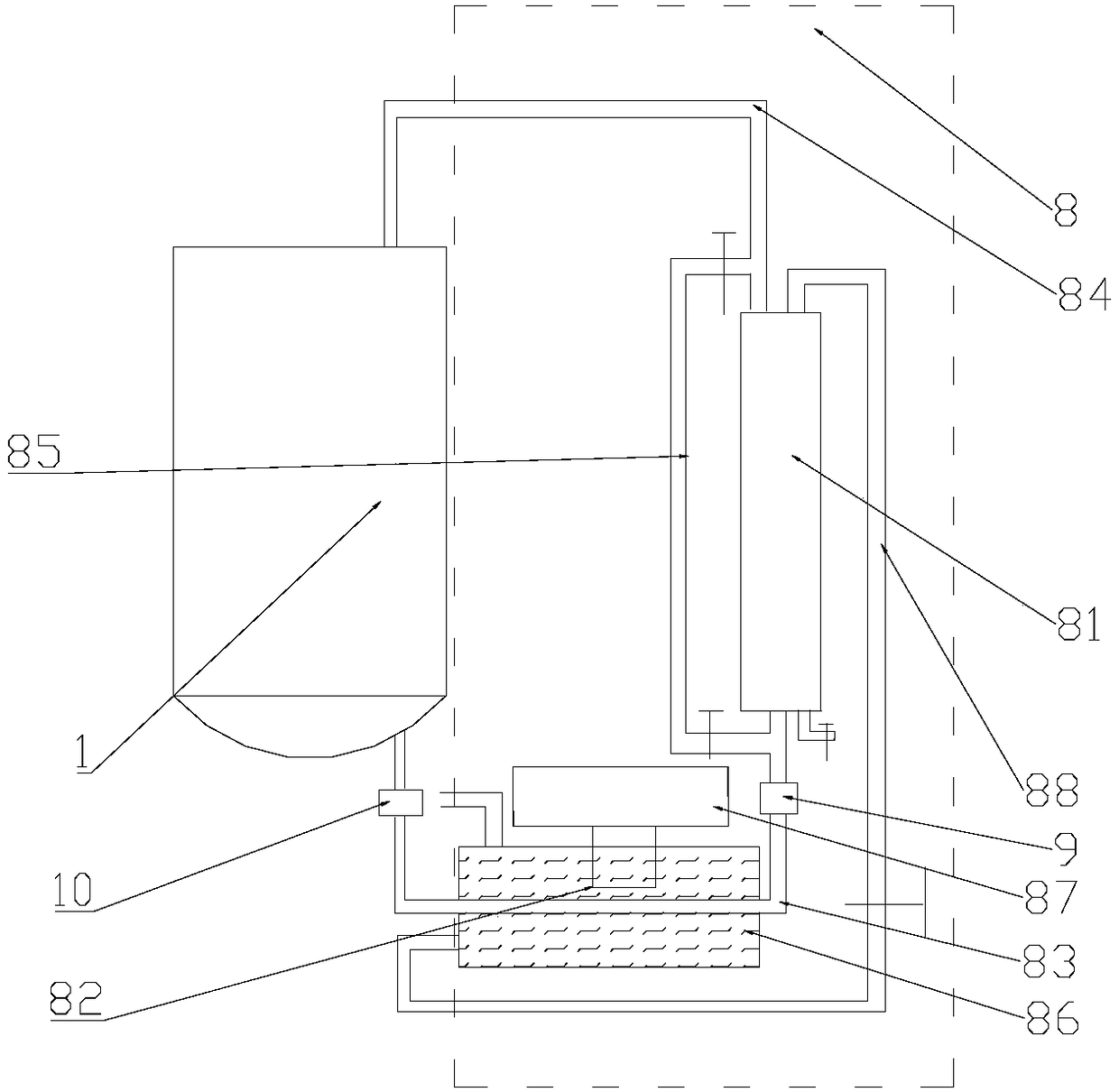
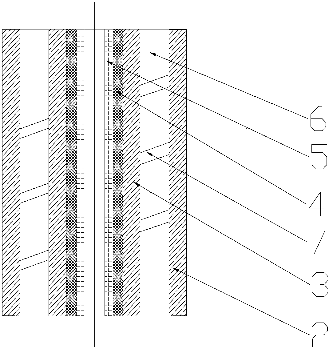
[0030] Embodiment: the present invention discloses a kind of embodiment of shaping tube (see attached figure 2 , 3, 4), can be applied in step 2), the shaping tube 1 is cooled by cooling water, the cooling water is recycled through the circulation system, and the impurity removal operation is carried out during the circulation process; the shaping tube 1 is from outside to inside The first metal tube 2, the second metal tube 3, the thermal insulation carbon tube 4 and the graphite carbon tube 5 are arranged in sequence, and the inner side wall of the first metal tube 2 and the outer side wall of the second metal tube 3 form a cooling layer 6, and the cooling The layer 6 is provided with diversion ribs 7 , and the diversion ribs 7 are spirally wound around the first metal pipe 2 . Cooling water flows through the cooling layer 6 , and the cooling water moves along the diversion ribs 7 . The invention reduces the influence of dirt on the heat exchange effect by removing impurit...


PUM

PropertyMeasurementUnit
diameteraaaaaaaaaa

Abstract

The invention discloses an optical fiber drawing technique, comprising the steps of 1) performing melt drawing, to be specific, melting a preform at 2200-2300 DEG C, and drawing by gravity sagging; 2)performing setting and cooling, to be specific, cooling the sagged yarn via a setting pipe to 500-600 DEG C; 3) performing drawing and cooling, to be specific, further cooling the yarn via a coolingdevice to 30-80 DEG C. The setting pipe in the step 2) is cooled by cooling water, the cooling water is cyclically utilized by a circulation system, and cleaning is performed during the cyclic use; acooling layer of the setting pipe has guide ribs inside, and the guide ribs are spiraled on a first metal pipe; the cooling water is introduced into the cooling layer and moves along the guide ribs. The optical fiber drawing technique designed herein has the advantages that the cooling water in the setting pipe is cleaned and cyclically utilized, the influence of scale upon heat exchange effect isrelieved, cooling effect of the cooling water is more effectively ensured, and the guide ribs in spiral arrangement can prevent deformation and exchange heat.

Description

technical field [0001] The invention relates to the field of optical fiber production, in particular to an optical fiber drawing process. Background technique [0002] Optical fiber, short for optical fiber, is a fiber made of glass or plastic that acts as a means of light transmission. The optical fiber is composed of two layers of glass with different refractive indices. The inner layer is the optical core with a diameter of several microns to tens of microns, and the outer layer has a diameter of 0.1 to 0.2 mm. Generally, the refractive index of the inner core glass is 1% larger than that of the outer glass. According to the principle of refraction and total reflection of light, when the angle at which the light hits the interface between the inner core and the outer layer is greater than the critical angle for total reflection, the light cannot pass through the interface and is fully reflected. At present, the optical fiber used in communication is generally silica opt...

Claims


Application Information

Patent Timeline
Patent Type & Authority Patents(China)
IPC IPC(8): C03B37/025
CPCC02F1/001C02F5/00C03B37/025C03B37/0253F28D1/053F28F27/00
Inventor 胡涛涛吴巧宾祝文青
Owner HANGZHOU FUTONG COMM TECH CO LTD
Why Eureka
Try Eureka