High pressure manifold device for carbon dioxide dry fracturing

A high-pressure manifold and carbon dioxide technology, which is applied in the direction of wellbore/well components, production fluid, earthwork drilling and production, etc., can solve the problems of labor-intensive operators, complex connection process of construction pipelines, and large damage to high-pressure pipe valves. Achieve the effect of reducing labor intensity, meeting the operation requirements and normal construction requirements on site, and reducing the risk of construction operations

Active Publication Date: 2016-08-17
BC P INC CHINA NAT PETROLEUM CORP +1
View PDF7 Cites 7 Cited by
  • Summary
  • Abstract
  • Description
  • Claims
  • Application Information

AI Technical Summary

Problems solved by technology

[0006] The purpose of the present invention is to overcome the problems existing in the existing carbon dioxide dry fracturing operation,

Method used


Image

  • High pressure manifold device for carbon dioxide dry fracturing

Examples


Embodiment 1

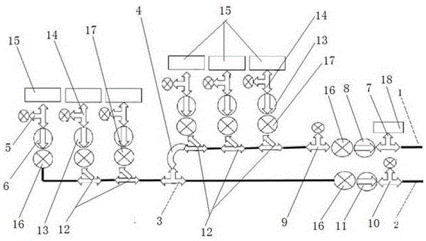
[0024] In order to solve the existing problems in the existing carbon dioxide dry fracturing operation, such as complex construction pipeline connection process, large damage to high-pressure pipe valve parts, and labor-intensive operators, this embodiment provides the following figure 1 A carbon dioxide dry fracturing high-pressure manifold device shown in the figure includes a main line 1 and a main line 2, one end of the main line 1 and one end of the main line 2 are respectively connected to the Christmas tree, A T-shaped tee 3 is connected in series in the middle section of the main line 2 of the II route. The T-shaped tee 3 is connected to the other end of the main line 1 of the I route through a double-female oil short-circuit 4, and the other end of the main line 2 of the II route is connected in series. Check valve one 6, check valve one 6 is connected with main press car 15 through T-type tee one 5;

[0025] The main line 1 of road I is connected in series with T-typ...

Embodiment 2

[0033] On the basis of Example 1, the T-shaped tee 27 adopts a 3*2*3-inch structure. In order to monitor the real-time pressure of the high-pressure pipeline in the fracturing construction, the 2-inch buckle of the T-shaped tee 27 is connected with Pressure sensor 19.

Embodiment 3

[0035] On the basis of Example 1, between the check valve two 8 and the T-type tee three 9, between the check valve one 6 and the manifold tee 12 on the main line 2 of the II road, between the check valve three A 3-inch cock-16 is respectively connected in series between the manifold tee 12 on the main line 2 of the 11 and II road. A 3-inch cock two 17 is connected in series between the inclined pipe port of each manifold tee 12 and the check valve four 13. Each pipeline is isolated with a 3-inch cock and depressurized with a 2-inch cock, which solves the risk of pipeline puncture or carbon dioxide freezing and gasification in some pipelines;


PUM


Abstract

The invention provides a high pressure manifold device for carbon dioxide dry fracturing. Real-time pressure of a high pressure pipeline in a fracturing construction is monitored by arranging a pressure sensor on a tee joint. A 3-inch cock is used on each pipeline to carry out isolation and a 2-inch cock is used on each pipeline to carry out pressure relief, and therefore the problems of piercing-caused leakage of the pipelines and risks caused by dry ice formation and gasification of carbon dioxide in a part of pipelines are solved. A check valve is arranged on each pipeline to prevent liquid from backflow; two primary pipelines are connected to ensure that the liquid in the two primary pipelines is averagely distributed. The high pressure manifold device has the characteristics of safety, standardization, reasonability, convenience, reliability and the like. The pipeline connection time can be greatly shortened, the damage degree of valve components for high pressure pipelines is reduced, the labor intensity of personnel is reduced and the construction efficiency is improved. Aiming at the characteristics of carbon dioxide, the safety control devices, such as a plurality of cock valves, the check valves and the pressure sensors, are arranged on the high pressure pipelines, so that the risks in the carbon dioxide dry fracturing construction can be greatly reduced, and the HSE (Health and Safety Executive) operation requirements in a fracturing field and the normal field construction requirements are met.

Description

technical field [0001] The invention belongs to the technical field of oil field fracturing, in particular to a carbon dioxide dry fracturing high-pressure manifold device. Background technique [0002] Because carbon dioxide dry fracturing has the advantages of no water phase, zero pollution, etc., and as people pay more attention to water resources and environmental issues, carbon dioxide anhydrous fracturing is becoming a cutting-edge fracturing technology to replace conventional hydraulic fracturing. The fracturing process fluid is liquid carbon dioxide with ultra-low temperature and high pressure, so there are high requirements for the materials and connection methods of high-pressure pipelines during the construction of this process. In order to make the connection of high-pressure pipelines for carbon dioxide fracturing safe, convenient and reasonable, it is necessary to standardize the connection of high-pressure manifold devices. [0003] The current carbon dioxide...

Claims


Application Information

Patent Timeline
IPC IPC(8): E21B43/26
CPCE21B43/26
Inventor 刘广春钟新荣姚伟詹勇郭春峰张铁军韩旭辉晏军刘兵王美琴李丹胡洪彬张世龙林勇
Owner BC P INC CHINA NAT PETROLEUM CORP
Why Eureka
Try Eureka