
Giant-magnetostriction driving and displacement amplifying device for direct drive valve

A technology of giant magnetostriction and giant magnetostrictive rod, applied in valve operation/release device, valve device, valve details, etc., can solve the problems of large heating current, temperature rise, and decrease of output displacement accuracy of driving mechanism. , to avoid friction, avoid oil leakage, and achieve the effect of miniaturization

Inactive Publication Date: 2016-08-17
PEOPLES LIBERATION ARMY ORDNANCE ENG COLLEGE
View PDF6 Cites 4 Cited by
  • Summary
  • Abstract
  • Description
  • Claims
  • Application Information

AI Technical Summary

Problems solved by technology

However, there are still some problems when the GMM-based drive mechanism drives the DDV: on the one hand, it is the problem of temperature rise. Due to the large drive current of the GMM rod, the heating phenomenon is more serious, and the output displacement accuracy of the drive mechanism caused by the thermal expansion of the GMM rod is greatly reduced. , it is usually necessary to suppress its thermal deformation; on the other hand, it is the problem of displacement amplification. Since the axial deformation produced by the GMM rod is not enough to drive the valve core to work, it is necessary to use a suitable micro-displacement amplification mechanism to control the output displacement of the GMM rod. enlarge

Method used


Image

  • Giant-magnetostriction driving and displacement amplifying device for direct drive valve
  • Giant-magnetostriction driving and displacement amplifying device for direct drive valve
  • Giant-magnetostriction driving and displacement amplifying device for direct drive valve

Examples


Embodiment Construction

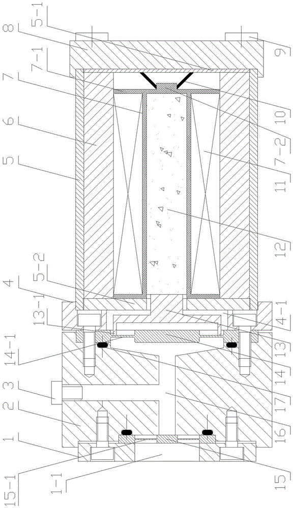
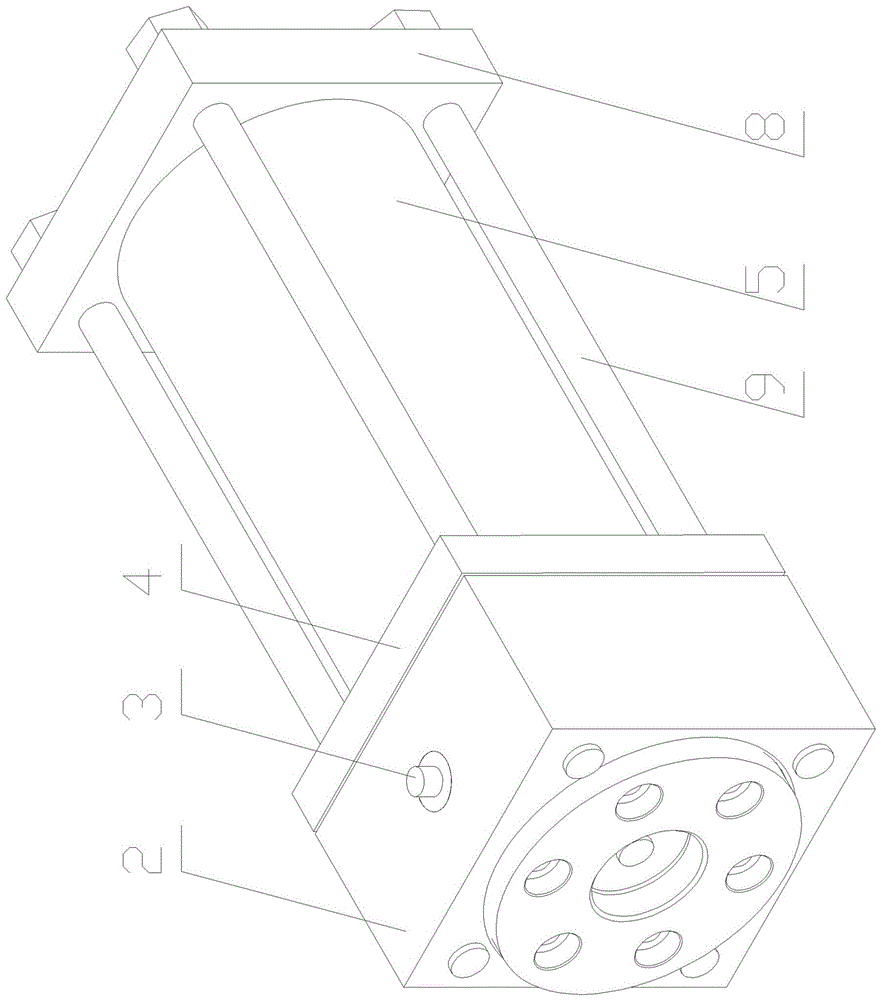
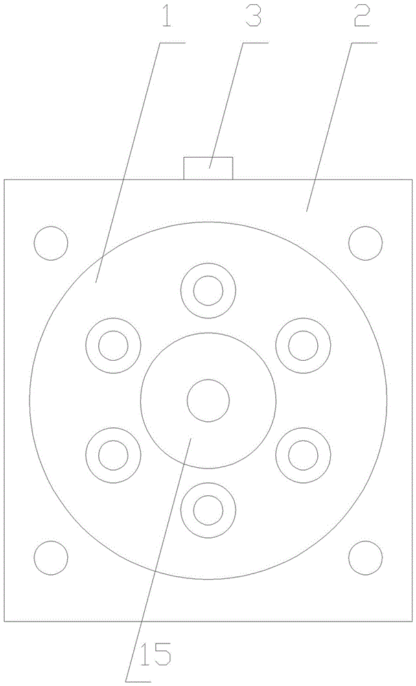
[0034] Depend on Figure 1-4 It can be seen from the illustrated embodiment that it includes a driving mechanism, a hydraulic amplifying mechanism and a square fixed plate 8;

[0035] The driving mechanism includes a circular tubular shell 5, a right end cap 5-1 and a left end cap 5-2 threadedly connected with the circular tubular shell 5, a first-stage output push rod 13, a giant magnetostrictive rod 12, and a thermally compensated Functional bobbin 7, excitation coil 11, circular tubular permanent magnet 6 and disc spring 10;

[0036] A push rod hole is provided at the center of the left end cover 5-2; the diameter of the push rod hole is greater than the diameter of the giant magnetostrictive rod 12;

[0037] The coil frame 7 is a cylindrical frame provided with a coil slot and a right baffle 7-1; a circular boss 7-2 matching the disc spring 10 is provided at the center of the right side of the right baffle 7-1; The giant magnetostrictive rod 12 is located in the cylinder...


PUM


Abstract

The invention discloses a giant-magnetostriction driving and displacement amplification device for a direct drive valve. The giant-magnetostriction driving and displacement amplification device for the direct drive valve comprises a driving mechanism, a hydraulic amplifying mechanism and the like. The driving mechanism comprises a round-pipe-shaped shell, a right end cover, a left end cover, a first-level output ejector rod, a giant-magnetostriction rod, a magnet exciting coil, a permanent magnet and the like. The hydraulic amplifying mechanism comprises a square oil cavity body, a round large diaphragm, a square large diaphragm cover, a round small diaphragm, a round small diaphragm cover, an oil cavity adjusting bolt and the like. By means of the giant-magnetostriction driving and displacement amplification device for the direct drive valve, the displacement output by the giant-magnetostriction rod can be amplified by 5-10 times, an electro-hydraulic servo valve can be directly driven to work, and miniaturization of the whole electro-hydraulic servo valve can be achieved. A flexible piston structure based on the large diaphragm and the small diaphragm is adopted, so that the problem of oil leakage of a traditional hydraulic amplifying mechanism is avoided; and due to the fact that a conical structure is adopted for an oil cavity, pressure losses caused by the phenomena of oil trapping and flow contracting during work of the amplifying mechanism are avoided.

Description

technical field [0001] The invention belongs to the technical field of direct-drive electro-hydraulic servo valve micro-drive, and relates to a giant magnetostrictive drive and displacement amplifying device for a direct-drive valve. Background technique [0002] The electro-hydraulic servo system has excellent characteristics such as small unit power mass, large force-to-mass ratio, wide operating frequency range, good robustness, and strong anti-overload ability. It has been widely used in modern aviation industry, automobile industry and other fields. Electro Hydraulic Servo Valve (EHSV) is the most important component in the electro-hydraulic servo system. It is a bridge between electronic devices and hydraulic devices, and plays a decisive role in the dynamic performance of the entire system. Most of the commonly used EHSVs are nozzle baffle valves. This kind of valve has high performance, but its disadvantage is that it is difficult to process and expensive; it require...

Claims


Application Information

Patent Timeline
Patent Type & Authority Applications(China)
IPC IPC(8): F16K31/10F16K31/06
CPCF16K31/0675F16K31/10
Inventor 何忠波杨朝舒李冬伟薛光明赵正龙周景涛荣策
Owner PEOPLES LIBERATION ARMY ORDNANCE ENG COLLEGE
Learn More