Heating segmented temperature control tunnel type drying channel of burner

A technology of segmented temperature control and burner, which is applied in heating devices, lighting and heating equipment, drying and other directions, can solve the problems of increasing production costs, high power, and high power consumption of production plants, and achieves reduction of production costs, The effect of solving the problem of power consumption

Inactive Publication Date: 2016-08-17
汪安瑞
View PDF11 Cites 2 Cited by
  • Summary
  • Abstract
  • Description
  • Claims
  • Application Information

AI Technical Summary

Problems solved by technology

This infrared heating method has relatively high power and consumes a lot of electric energy, thus increasing the production cost of the factory.

Method used


Image

  • Heating segmented temperature control tunnel type drying channel of burner
  • Heating segmented temperature control tunnel type drying channel of burner
  • Heating segmented temperature control tunnel type drying channel of burner

Examples


Embodiment 1

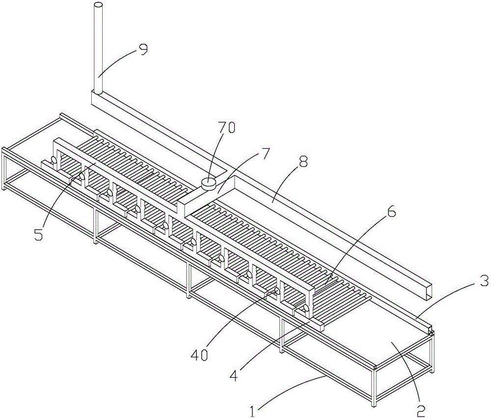
[0023] Such as figure 1 As shown, a burner heating segmental temperature-controlled tunnel-type drying tunnel, which includes a drying tunnel support frame 1, and a conveyor belt 2 for transporting color crystal glass is provided on the drying tunnel support frame 1. In the described A hot air pipe 3 is arranged on one side of the drying tunnel support frame 1, and several inverted "T"-shaped pipes 4 are arranged on the other side, and the top ends of the several inverted "T"-shaped pipes 4 are connected by a first connecting pipe 5. , and communicated, on the side below each group of inverted "T" tubes 4, several cooling air pipes 6 are connected to the hot air pipes 3, and on the first connecting pipe 5, the second connection The pipe 7 is connected with the hot air return pipe 8, and one end of the hot air pipe 3 is closed, and the other end is connected with the burner or the biomass pellet burner, and the heat source is provided by the burner or the biomass pellet burner....

Embodiment 2

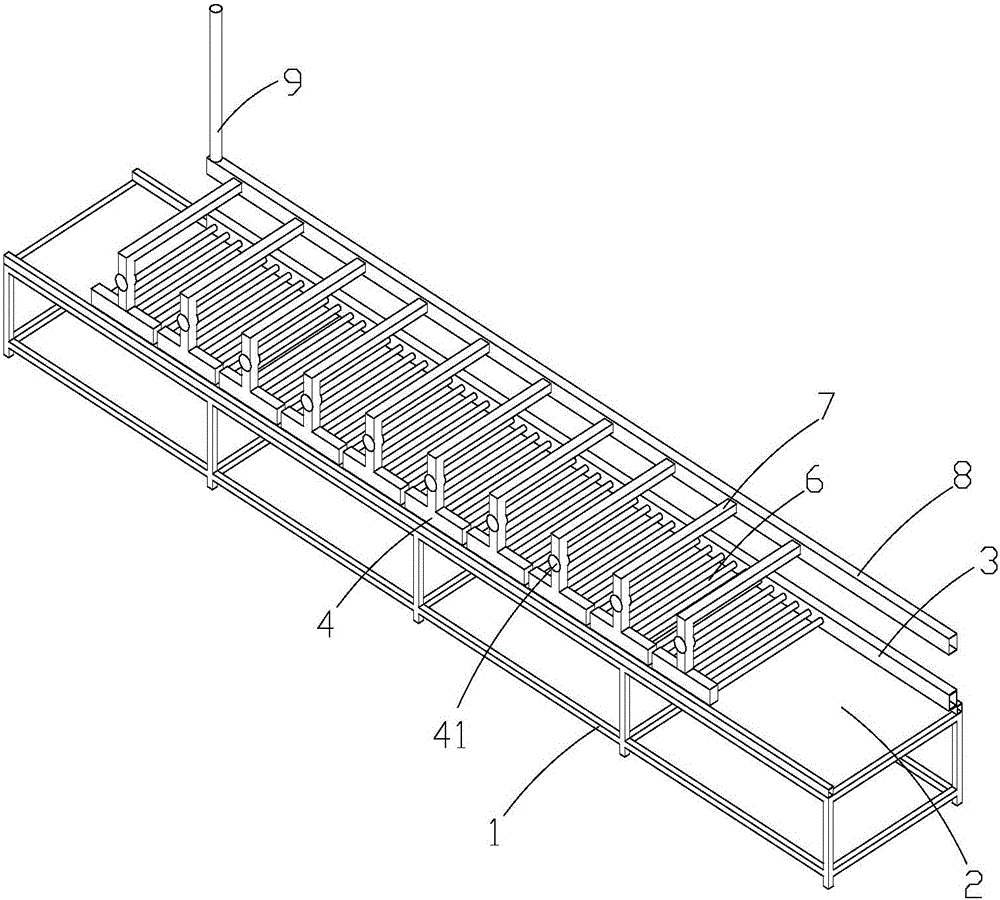
[0026] Such as figure 2 As shown, the top of each inverted “T” pipe 4 is connected to the heat return pipe through the second connecting pipe 7 , and each inverted “T” pipe 4 is provided with a temperature-controlled fan 41 .

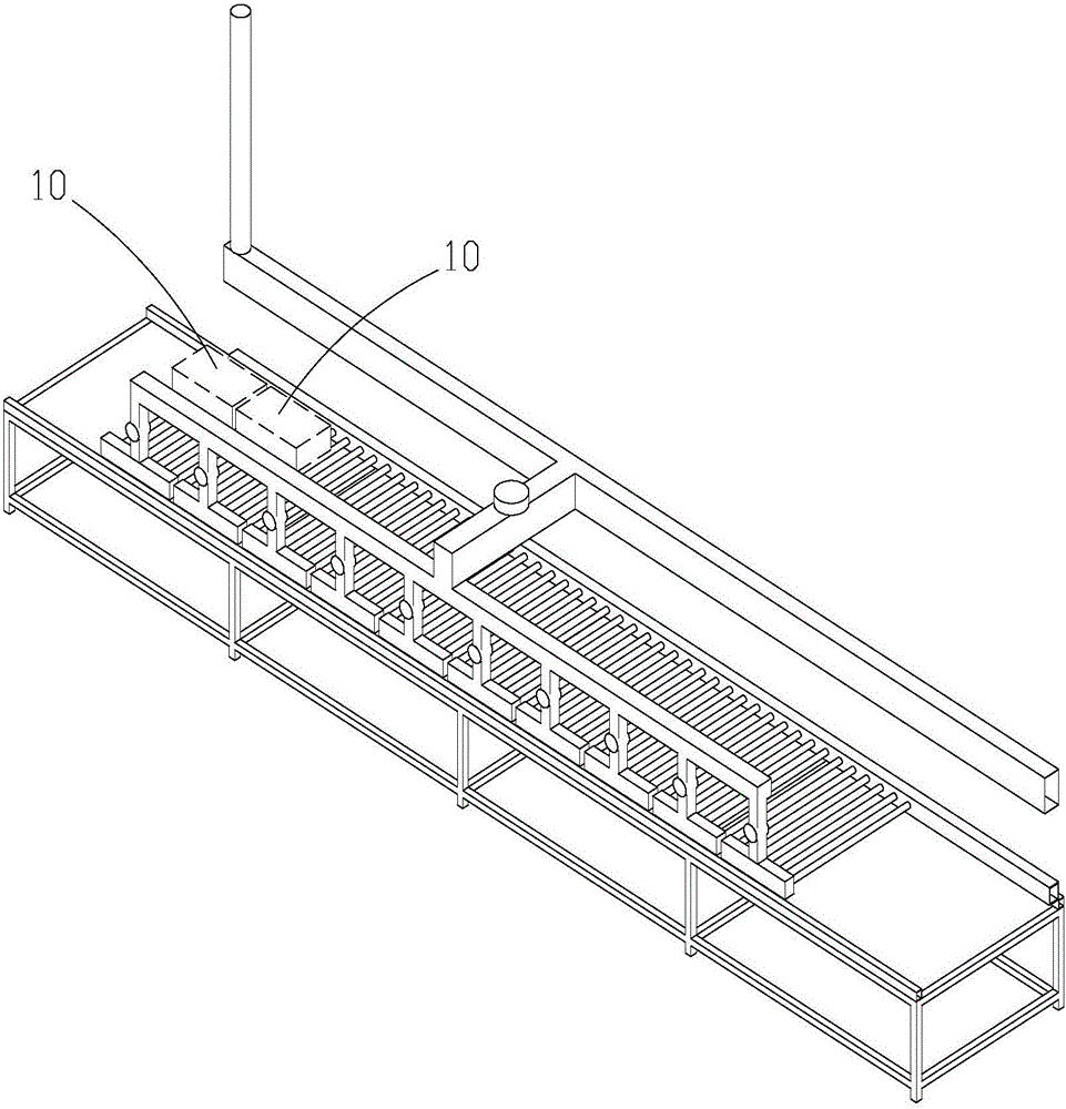
[0027] Such as Figure 1-3 As shown, the present invention provides a heat source through a burner or a biological particle burner. In the case of providing a heat source, the present invention has two temperature control modes, and these two temperature control modes are as follows:

[0028] When the temperature control valve 40 controls the temperature: the heat source of the burner or the bio-particle burner will be evenly distributed on each heat dissipation air pipe 6, and the hot gas generated by the burner or the bio-particle burner will pass through the hot air pipe 3 to dissipate heat. Air pipe 6, inverted "T" pipe 4, first connecting pipe 5, second connecting pipe 7 and heat return air pipe 8 are then discharged from heat exhaust pipe 9, or ...


PUM


Abstract

The invention discloses a heating segmented temperature control tunnel type drying channel of a burner. The drying channel comprises a drying channel supporting frame. A conveyor belt used for conveying color crystal glass is arranged on the drying channel supporting frame. A hot air pipe is arranged on one side of the drying channel supporting frame. A plurality of inverted-T-shaped pipes are arranged on the other side of the drying channel supporting frame. The top ends of the inverted-T-shaped pipes are connected through a first connecting pipe and communicate with one another through the first connecting pipe. One side of the lower portion of each inverted-T-shaped pipe is connected with the hot air pipe through a plurality of radiating pipes. The first connecting pipe is connected with a return hot air pipe through a second connecting pipe. One end of the hot air pipe is closed, and the other end of the hot air pipe is connected with the burner or a bio-particle burner. A heat source is provided by the burner or the bio-particle burner. The drying channel is simple in structure, convenient and accurate to control and capable of greatly reducing energy consumption.

Description

technical field [0001] The invention relates to a glass drying device, in particular to a burner-heated segmental temperature-controlled tunnel-type drying tunnel, which is mainly used for drying colored crystal glass with patterns on it. Background technique [0002] Colored crystal glass with rich patterns is a popular building material in modern home decoration, and the degree of realistic pattern effect is unmatched by other art glass. Usually, the manufacturing process of colored crystal glass mainly includes three major processes: cleaning, coloring, and drying, and the "drying" process is the core of the core. At present, the drying process in the market often uses infrared heating to achieve the drying of colored crystal glass. This infrared heating method has relatively high power and needs to consume a large amount of electric energy, thereby increasing the production cost of the production plant. Contents of the invention [0003] Based on the technical proble...

Claims


Application Information

Patent Timeline
Patent Type & Authority Applications(China)
IPC IPC(8): F26B15/18F26B21/10F26B23/02
CPCF26B15/18F26B21/10F26B23/02
Inventor 汪安瑞
Owner 汪安瑞
Why Eureka
Try Eureka