Check patentability & draft patents in minutes with Patsnap Eureka AI!

capacitive sensing device

A technology of capacitive sensing and capacitance, applied in the direction of using electrical devices, measuring devices, using electromagnetic means, etc., can solve problems such as sensing

Active Publication Date: 2019-02-01
全普半导体科技(深圳)有限公司
View PDF11 Cites 0 Cited by
  • Summary
  • Abstract
  • Description
  • Claims
  • Application Information

AI Technical Summary

Problems solved by technology

In the MEMS micro-scanning system, the torque arm setting is canceled, and the angular displacement information of the scanning disc or gimbal rotating along the first axis and the second axis cannot be sensed by the piezoelectric effect.

Method used


Image

  • capacitive sensing device
  • capacitive sensing device
  • capacitive sensing device

Examples


Embodiment Construction

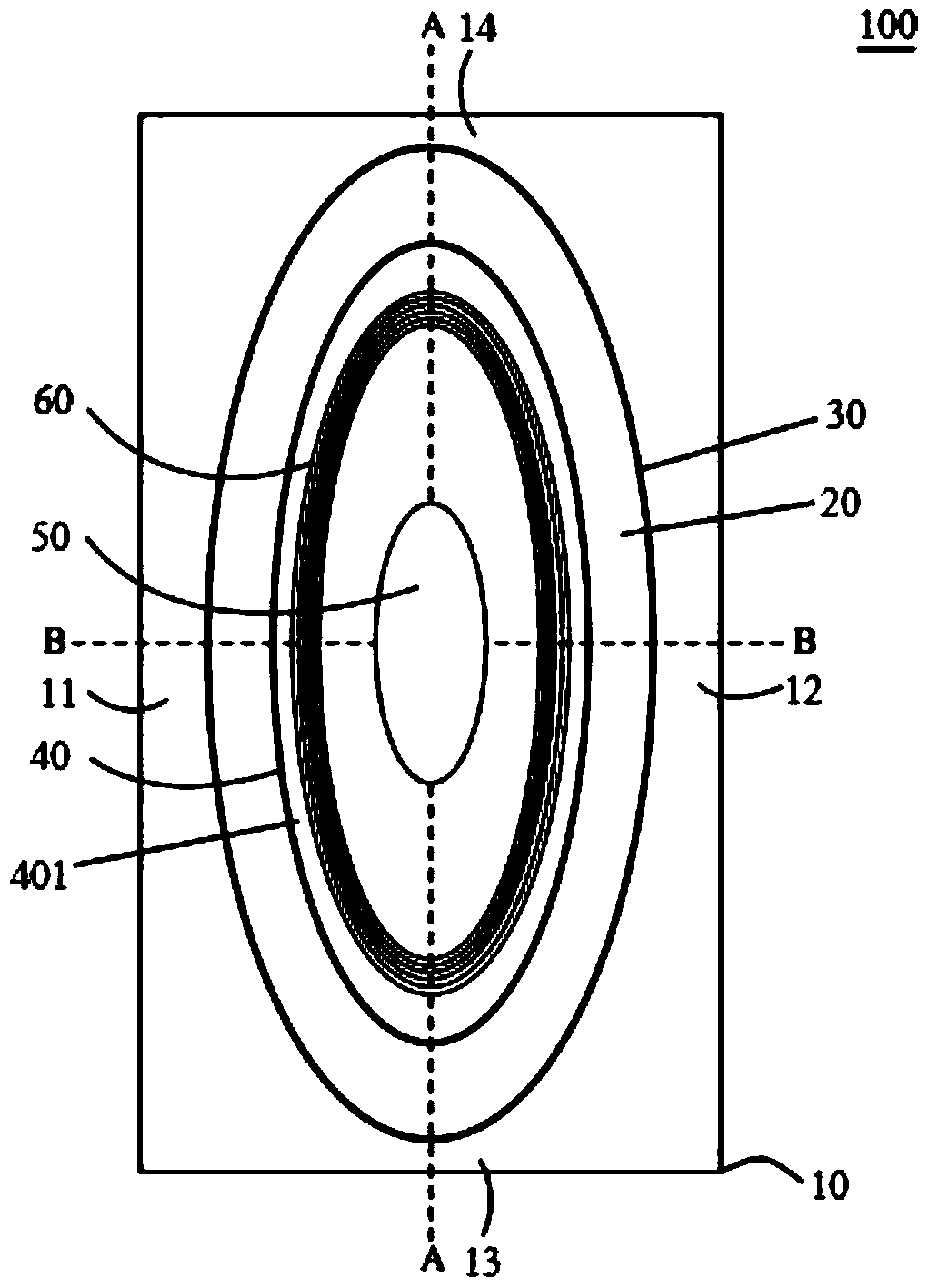
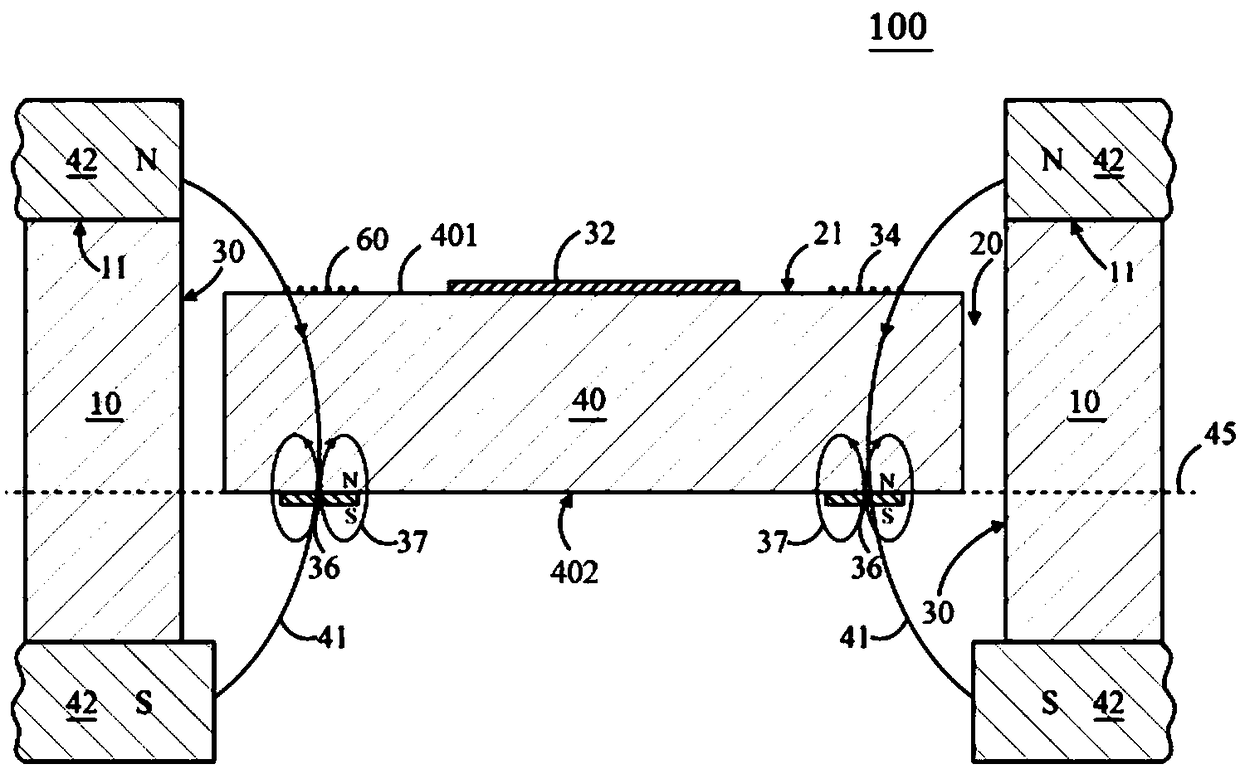
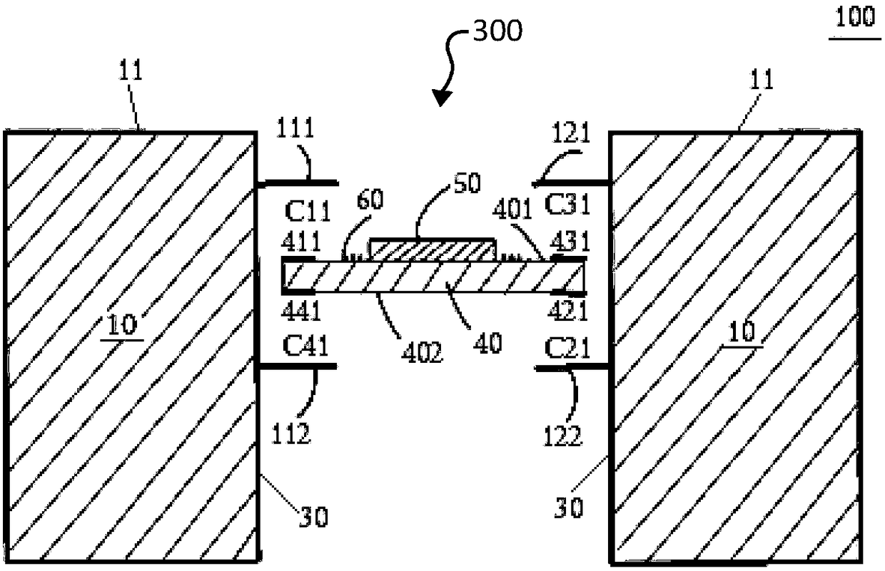
[0047] Here, different exemplary embodiments of the present invention are explained below with reference to the drawings, in which the same reference numerals denote elements with similar structures or functions in the respective figures. It should be noted that the accompanying drawings are intended to illustrate preferred embodiments of the invention. They are not intended to be exhaustive or to limit the scope of the invention. In addition, the drawings do not necessarily represent actual dimensions and proportional relationships. In addition, it is to be understood that terms such as top, bottom, upper, lower, left, right, front, rear, vertical, horizontal, etc. are for convenience in describing various elements of the invention with reference to the drawings. They are not intended to limit the orientation of the various elements of the invention or the spatial relationship between elements.

[0048] The present invention provides a capacitive sensing device for sensing ...


PUM


Abstract

A capacitance sensing device (300) comprises multiple sensing circuits (310 and 510) coupled to multiple series capacitor banks (C<0>1 and C<0>2). A capacitor (C31) in the series capacitor bank (C<0>2) is provided with a movable electrode (431) which is arranged on a scanning plate (40) or a balancing ring (70) of a micro-scanner (100) and a fixed electrode (131 ) which is arranged on one side wall (30) of a cavity (20) of a base (10), and a capacitor (C41) in the series capacitor bank (C<0>2) is provided with a movable electrode (441) which is arranged on a scanning plate (40) or a balancing ring (70) of another micro-scanner (200) and a fixed electrode (142 ) which is arranged on one side wall (30) of a cavity (20) of another base (10). Changes of capacitance values of the series capacitor banks (C<0>1 and C<0>2) are caused by deflection of the scanning plates (40) or the balancing rings (70). The sensing circuits (310 and 510) output multiple voltage values corresponding to capacitors of the series capacitor banks (C<0>1 and C<0>2). An output signal of the capacitance sensing device (300) provides angle information of laser beams projected by the scanner (100) and the scanner (200) for a feedback circuit.

Description

technical field [0001] The invention relates to a sensing device, in particular to a capacitive sensing device for angular displacement sensing of a microscanner. Background technique [0002] In the laser micro-projection device, the MEMS micro-scanning system (Micro Electronic Mechanical System, micro-motor system) is usually a two-axis micro-motor system, and a scanning plate of the micro-scanning system rotates along the first axis during the scanning process to form complex numbers in a row. pixels, and a balance ring rotates along a second axis perpendicular to the first axis to form a plurality of pixel rows to project projection beams containing image pixel information. In order to ensure the accuracy of the output projection picture, the optical sensor is used to sense the laser signal emitted by the laser light source, the angular displacement sensor is used to sense the angular displacement signal of the scanning plate and the balance ring during the rotation proc...

Claims


Application Information

Patent Timeline
Patent Type & Authority Patents(China)
IPC IPC(8): G01B7/30G02B26/08G02B26/10
CPCG01B7/30G02B26/0833G02B26/10
Inventor 汪际军
Owner 全普半导体科技(深圳)有限公司
Features
  • R&D
  • Intellectual Property
  • Life Sciences
  • Materials
  • Tech Scout
  • Unparalleled Data Quality
  • Higher Quality Content
  • 60% Fewer Hallucinations
Learn More