RFID card reading apparatus and card reading method

A card reading device and card reading technology, applied in the field of radio frequency identification, can solve the problems of high cost and complex structure, and achieve the effects of reliable performance, simple structure and large reading range

Inactive Publication Date: 2016-08-17
NANJING SIGNWAY SHITONG INFORMATION TECH CO LTD
View PDF5 Cites 4 Cited by
  • Summary
  • Abstract
  • Description
  • Claims
  • Application Information

AI Technical Summary

Problems solved by technology

At present, a common card reader is a reader-writer driving an antenna. To achieve multi-point reading of IC card / electronic tag information, multiple readers and reading heads are required to access, and the structure is complex and costly.

Method used


Image

  • RFID card reading apparatus and card reading method
  • RFID card reading apparatus and card reading method
  • RFID card reading apparatus and card reading method

Examples


Embodiment 1

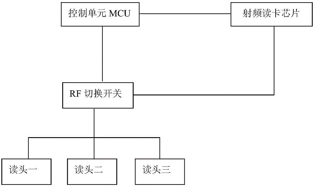
[0019] Such as figure 1 , 3 As shown, the RFID card reading device includes a control unit MCU, a radio frequency card reading chip, an RF switch, and three reading heads (reading heads one to three); the control unit MCU is connected with the radio frequency card reading chip and the RF switching switch respectively, wherein the control The unit MCU is connected to the RF card reader chip through the SPI bus; the RF switching switch is connected to the first reading head, the second reading head and the third reading head respectively; the radio frequency card reading chip is connected to the RF switching switch; the control unit MCU periodically controls the The connection and disconnection between the radio frequency card reading chip and each reading head (reading heads one to three) are described. The RFID card reading device also includes a host computer communication interface (not shown in the figure), and the host computer communication interface is connected with th...

Embodiment 2

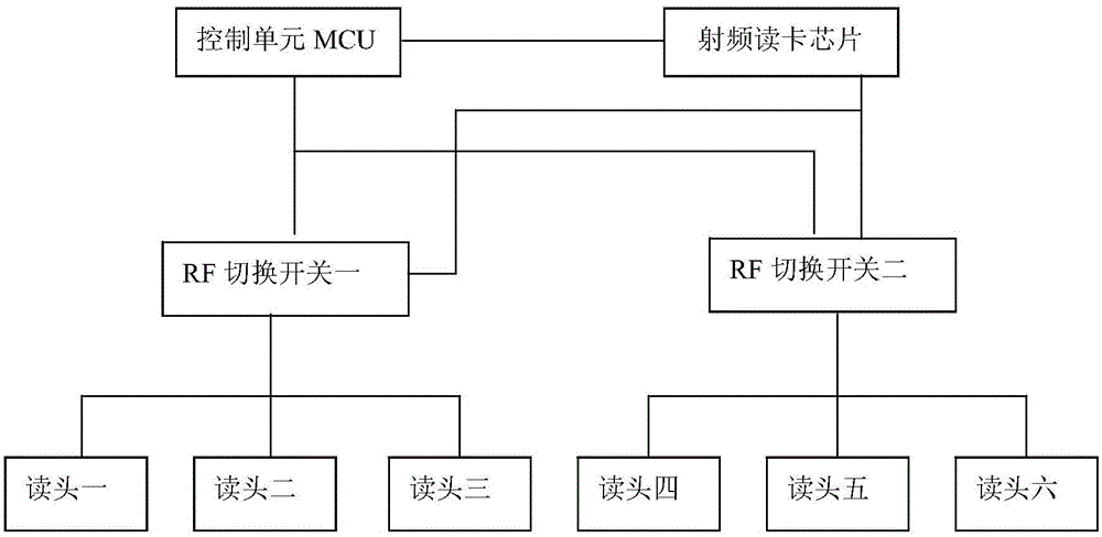
[0022] Such as figure 2 , 3 As shown, the RFID card reading device includes a control unit MCU, a radio frequency card reading chip, an RF switch one, an RF switch two, and six reading heads (reading heads one to six); the control unit MCU is respectively connected to the radio frequency card reading chip and the RF switch Switch 1 and RF switching switch 2 are connected, wherein, the control unit MCU and the radio frequency card reader chip are connected through the SPI bus; RF switching switch 1 is respectively connected to the reading head 1, reading head 2, and reading head 3, and the RF switching switch 2 is respectively connected to the reading head Four, the reading head five, the reading head six; the radio frequency card reading chip is connected with the RF switching switch one and the RF switching switch two; the control unit MCU periodically controls the radio frequency card reading chip and each The connection and disconnection between the reading heads (reading...


PUM


Abstract

The present invention provides an RFID card reading device and a card reading method. One or more RF switching switches are connected in series between the radio frequency card reading chip and the reading head, and at least one RF switching switch is periodically controlled by the control unit MCU to poll and switch each The connection and disconnection of the reading head and the radio frequency card reading chip make the radio frequency card reading chip and multiple reading heads respectively connected in one cycle, so that each reading head works in time, which can avoid the collision problem in the control processing module, It can also ensure that the effective power of the read head is not reduced, thereby obtaining a larger reading range and better reading effect. The invention has simple structure, low cost and reliable performance.

Description

technical field [0001] The invention belongs to the technical field of radio frequency identification, and relates to an RFID card reading device and a card reading method. Background technique [0002] Radio Frequency Identification (RFID) is a communication technology that can identify specific targets and read and write related data through radio signals without the need for mechanical or optical contact between the identification system and specific targets. Usually the RFID system consists of three parts: IC card / electronic tag, reader and middleware. As the main channel between the back-end middleware and application system and the front-end IC card / electronic tag, the reader plays a pivotal role. Generally, the reader can be divided into three modules: wireless module, radio frequency channel module, and control processing module. The radio frequency channel module and the control processing module are directly integrated in the reader. Some types of readers are in...

Claims


Application Information

Patent Timeline
Patent Type & Authority Applications(China)
IPC IPC(8): G06K7/00
CPCG06K7/0086
Inventor 白坤於恩铭
Owner NANJING SIGNWAY SHITONG INFORMATION TECH CO LTD
Why Eureka
Try Eureka