Manufacture method of X-ray optical spatial filter, direction adjustment method of X-ray optical spatial filter and device

A technology of a spatial filter and a manufacturing method, which is applied in the field of medical instruments and can solve problems such as the inability to flexibly adjust the number of rows and columns of the light guide tube array, the inability to flexibly change the length of the light guide tube, and the inability to flexibly change the direction of the light guide tube

Inactive Publication Date: 2016-08-17
钱浙滨
View PDF0 Cites 0 Cited by
  • Summary
  • Abstract
  • Description
  • Claims
  • Application Information

AI Technical Summary

Problems solved by technology

[0006] The present invention provides an X-ray spatial filter manufacturing method, direction adjustment method and device, which are used in X-ray imaging to filter out the interference of the scattered component on the direct component, and the purpose is to overcome the inflex

Method used


Image

  • Manufacture method of X-ray optical spatial filter, direction adjustment method of X-ray optical spatial filter and device
  • Manufacture method of X-ray optical spatial filter, direction adjustment method of X-ray optical spatial filter and device
  • Manufacture method of X-ray optical spatial filter, direction adjustment method of X-ray optical spatial filter and device

Examples


Embodiment 1

[0041] Embodiment 1, an example of a manufacturing method of an X-ray spatial filter

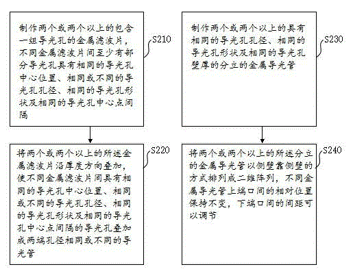
[0042] see figure 2 As shown, the embodiment of the X-ray spatial filter manufacturing method provided by the present invention includes:

[0043] The filter stacking method includes the following steps:

[0044] Step S210, making two or more metal filters containing a set of light guide holes, at least some of the light guide holes between different metal filters have the same central position of the light guide holes, the same or different apertures of the light guide holes , the same shape of the light guide hole and the same distance between the center points of the light guide hole;

[0045] Step S220, stacking two or more metal filters along the thickness direction, so that different metal filters have the same central position of the light guide hole, the same or different diameters of the light guide hole, and the same light guide hole The light guide holes with the same shape an...

Embodiment 2

[0061] Embodiment 2, an example of an X-ray spatial filter direction adjustment method

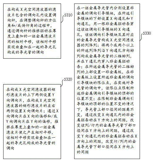
[0062] see image 3 As shown, the X-ray spatial filter steering method embodiment provided by the present invention includes:

[0063] The filter translation and direction adjustment method is used for an X-ray spatial filter with a filter superposition structure, comprising the following steps:

[0064] Step S310, setting the steering rod in the steering hole contained in the filter that constitutes the X-ray spatial filter. During the process of adjusting the azimuth and / or elevation angle of the steering rod, the steering rod is pushed to drive the The relative translation between a group of metal filters superimposed on the thickness realizes the direction adjustment of the light pipe composed of superimposed light guide holes; or,

[0065] Step S320, setting Y-direction directional plates on the upper and lower sides of the rectangular filter constituting the X-ray spatial filter, a...

Embodiment 3

[0075] Embodiment 3, a configuration example of an X-ray spatial filter

[0076] The configuration example of the X-ray spatial filter given in this embodiment includes:

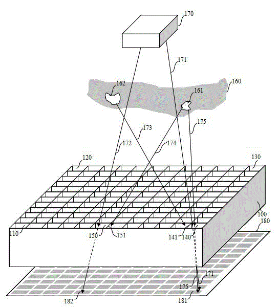
[0077] Filter tube arrangement structure, see Figure 4 As shown, the structure includes: two or more separate metal light pipes 430 and 431, 432, 433, 410 having the same light guide hole diameter, the same light guide hole shape and the same light guide hole wall thickness , 420, 440;

[0078] The two or more discrete metal light pipes are arranged in a two-dimensional array 400 with side walls side by side, the relative positions of the upper ports of different metal light pipes remain unchanged, and the lower ports The spacing can be adjusted;

[0079] Alternatively, the filter stack structure, see Figure 6 As shown, the structure includes: two or more metal filters 620, 630 containing a set of light guide holes;

[0080]The metal filters 620, 630 are used to form the X-ray spatial filter 600 in a ...


PUM


Abstract

The invention provides a manufacture method of an X-ray optical spatial filter, a direction adjustment method of the X-ray optical spatial filter and a device. With the methods and device adopted, at least one defect selected from a defect of incapability of flexibly changing the directions of light guide tubes, incapability of flexibly changing the lengths of the light guide tubes and incapability of flexibly adjusting the numbers of the lines and columns of a light guide tube array of an existing X-ray optical spatial filter can be eliminated. The manufacture method of the X-ray optical spatial filter provided by the invention includes a filtering sheet superposition method or a filtering tube arrangement method. According to the X-ray optical spatial filtering device provided by the invention, the directions and lengths of light guide tubes can be flexibly changed, or the numbers of the lines and columns of a light guide tube array can be flexibly adjusted.

Description

technical field [0001] The invention relates to the field of medical instruments, in particular to a method for manufacturing an X-ray spatial filter, an orientation method and a device. Background technique [0002] The rays radiated from different parts of the X-ray source will overlap in space, and X-rays will also be scattered during the process of penetrating objects / human tissues. This scattered light will overlap in space with direct light. When these When overlapping occurs on the sensing unit of the X-ray imaging sensor, it causes the X-ray image to be disturbed by scattered light. In order to suppress the interference caused by the overlapping of scattered light and direct light at the imaging sensor unit, a grid-shaped X-ray spatial filter structure has been adopted in the industry, see figure 1 As shown, the grid-shaped X-ray spatial filter 100 is placed between the X-ray imaging sensor array 180 and the detected object 160, and the grid-shaped X-ray spatial fil...

Claims


Application Information

Patent Timeline
IPC IPC(8): G21K3/00
Inventor 钱浙滨
Owner 钱浙滨
Why Eureka
Try Eureka