
Multi-source coordination control method for direct-current microgrid

A technology of DC micro-grid and coordinated control, which is applied in parallel operation of DC power supplies, collectors, electric vehicles, etc., and can solve problems such as system collapse, control failure, and impact on system power quality

Active Publication Date: 2016-08-17
ELECTRIC POWER RES INST OF STATE GRID ZHEJIANG ELECTRIC POWER COMAPNY +1
View PDF3 Cites 26 Cited by
  • Summary
  • Abstract
  • Description
  • Claims
  • Application Information

AI Technical Summary

Problems solved by technology

Among them, the centralized control is controlled through the central controller and high-speed communication. The central controller collects the operating status of each micro-source and sends control instructions to each micro-source. However, the centralized control is very dependent on the central controller and high-speed communication. Once one of the two fails, the control will fail, and the system will face the danger of collapse.
The current distributed control can effectively avoid the shortcomings of centralized control communication failures. Most of them use the principle that the DC bus voltage is the only index that reflects the energy balance in the DC microgrid, and realize the coordination of each micro-source according to the change of the DC bus voltage. control, but it will inevitably bring large-scale fluctuations to the voltage of the DC bus, which will affect the power quality of the system

Method used


Image

  • Multi-source coordination control method for direct-current microgrid
  • Multi-source coordination control method for direct-current microgrid
  • Multi-source coordination control method for direct-current microgrid

Examples


Embodiment Construction

[0041] The core of the present invention is to provide a DC microgrid multi-source coordinated control method, which effectively reduces the large-scale fluctuation of the DC bus voltage under the premise of maximizing the use of renewable energy and maintaining the energy balance in the DC microgrid system Finally, the bus voltage of the DC microgrid system is guaranteed to be stable at the rated value, and the power quality of the system is improved.

[0042] In order to make the objectives, technical solutions, and advantages of the embodiments of the present invention clearer, the technical solutions in the embodiments of the present invention will be described clearly and completely in conjunction with the accompanying drawings in the embodiments of the present invention. Obviously, the described embodiments It is a part of the embodiments of the present invention, not all the embodiments. Based on the embodiments of the present invention, all other embodiments obtained by t...


PUM


Abstract

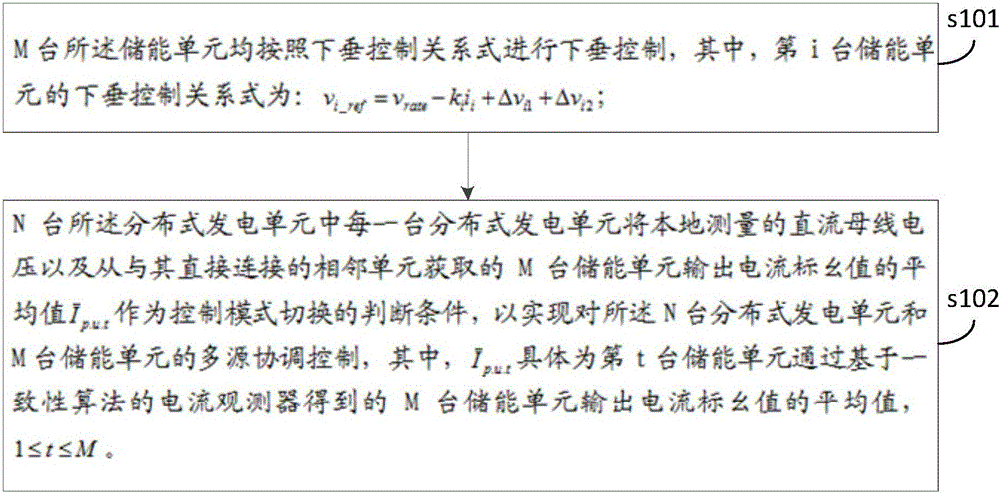
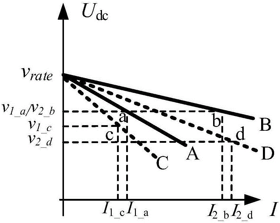
The invention discloses a multi-source coordination control method for a direct-current microgrid. The method is applied to the direct-current microgrid including N distributive power generating units and M energy storing units. The method comprises steps as follows: the M energy storing units perform droop control in accordance with the droop control relation; each of the N distributive power generating units adopts the local measured direct-current bus voltage and the average, shown in the specification, of output current per-unit values of the M energy storing units obtained from adjacent units directly connected with the distributive power generating unit as switching judging conditions for a control mode, so that multi-source coordination control over the N distributive power generating units and M energy storing units is realized; the average of the output current per-unit values of the M energy storing units obtained through a current observer on the basis of a consistency algorithm by the tth energy storing unit is shown in the specification. With the adoption of the method, on the premise that renewable energy sources are used to the greatest extent and energy balance in a direct-current microgrid system is maintained, large-range fluctuation of the voltage of a direct-current bus is effectively reduced, and the quality of system electric energy is improved.

Description

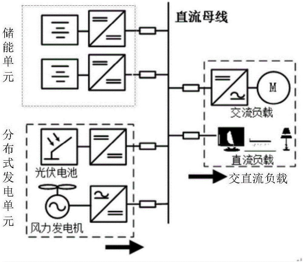
Technical field [0001] The invention relates to the technical field of micro-grid coordinated control, in particular to a method for multi-source coordinated control of DC micro-grid. Background technique [0002] With the large-scale utilization of various forms of renewable energy such as solar energy and wind energy, microgrids have received widespread attention at home and abroad as an effective way for distributed power sources to connect to the grid. Since most of these renewable energy sources output direct current (or there are intermediate links of direct current), and many household appliances and office equipment essentially require direct current power to work normally. Therefore, if the microgrid uses DC as the transmission form of electric energy, it can reduce conversion links and improve energy efficiency. [0003] The DC microgrid can work in grid-connected mode or independent mode. Among them, the control strategy of the DC microgrid working in independent mode i...

Claims


Application Information

Patent Timeline
IPC IPC(8): H02J1/10H02J7/34
CPCH02J1/10H02J7/34H02J7/345
Inventor 陈安伟李继红池伟郭力张雪松张绍辉周金辉
Owner ELECTRIC POWER RES INST OF STATE GRID ZHEJIANG ELECTRIC POWER COMAPNY
Learn More