Integrated multifunctional power source switching system
A power conversion system and multi-functional technology, applied in the direction of output power conversion device, control/regulation system, DC power input conversion to DC power output, etc., can solve the problems of occupying valuable space, increasing the weight and cost of electric vehicles, etc. Achieve the effect of saving system cost, light weight and reducing system volume
- Summary
- Abstract
- Description
- Claims
- Application Information
AI Technical Summary
Problems solved by technology
Method used
Image
Examples
Embodiment 1
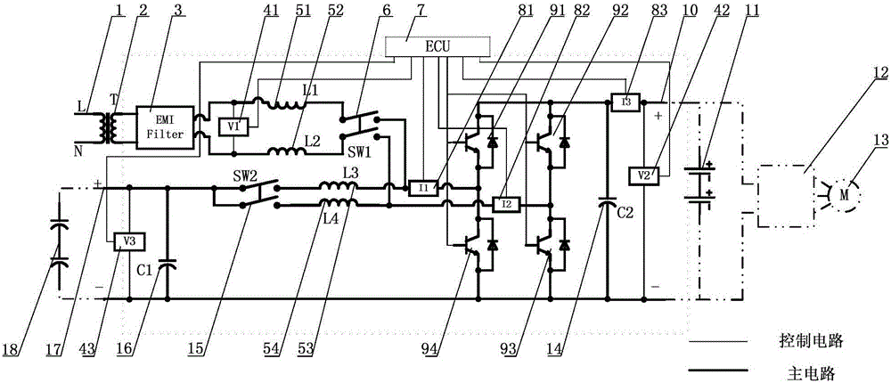
[0038] The integrated multifunctional power conversion system is applied to the composite power system composed of battery packs and super capacitors. The integrated multifunctional power conversion system performs DC power conversion between the super capacitor and the battery pack, and converts AC input power into DC power. Charging the battery pack, inverting the DC power of the battery pack into AC output.
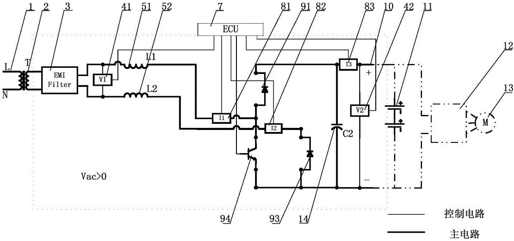
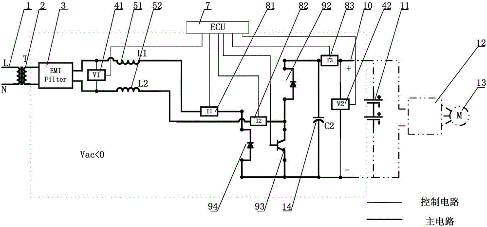
[0039] Such as figure 1 As shown, the integrated multifunctional power conversion system includes an AC interface 1, a transformer 2, an EMI filter 3, a first AC-side inductor 51, a second AC-side inductor 52, an AC-side switch 6, and a first DC-side filter capacitor 16 , The first DC terminal interface 17, the super capacitor group 18, the DC terminal switch 15, the first DC terminal inductor 53, the second DC terminal inductor 54, the second DC terminal interface 10, the battery pack 11, the motor controller 12, Three-phase motor 13, second DC terminal filter capacitor ...
Embodiment 2
[0054] The inductance value is determined by the following formula:
[0055] L = V i n X D I L X r X f
[0056] In the formula, L is the inductance value, V in Is the input voltage, D is the duty cycle, I L Is the inductor current, r is the current ripple rate, and f is the switching frequency.
[0057] When the voltage level, current, switching frequency, ripple rate and other parameters of the designed AC path and DC path are similar, the AC-side inductance value and the DC-side inductance value are also similar. By adjusting the design parameters, the first AC-side inductance 51, The two AC-side inductors 52 can be replaced by the first DC-side inductor 53 and the second DC-side inductor 54, such as Figure 5 As shown, thereby further saving system space and cost.
[0058] In the AC path of this embodiment, the AC interface 1 is connected to the first DC-side inductor 53 and the first DC-side inductor 54 after passing through the transfor...
Embodiment 3
[0062] When the peak input AC voltage is (V acL Is the lowest value of the effective value of AC voltage, V acH Is the highest value of AC voltage effective value), the second DC terminal voltage range is V dcL ~V dcH (V dcL Is the lowest voltage of the second DC terminal, V dcH Is the highest voltage of the second DC terminal), and satisfies When the AC-side transformer is not required, the AC interface 1 is directly connected to the EMI filter 3. Such as Image 6 As shown, compared with the implementation example 2, since the voltage level of the AC interface 1 and the voltage level of the second DC terminal 10 meet the above requirements, the AC terminal transformer may not be used, and both ends of the AC interface 1 are directly connected to the EMI filter 3 Both ends are connected, and the connection method of other devices is the same as that of embodiment 2. When the system works in the bidirectional DC / DC mode, the AC side switch 6 is opened, and the DC side s...
PUM
 Abstract
Description
Claims
Application Information
 - R&D
- Intellectual Property
- Life Sciences
- Materials
- Tech Scout
- Unparalleled Data Quality
- Higher Quality Content
- 60% Fewer Hallucinations
Browse by: Latest US Patents, China's latest patents, Technical Efficacy Thesaurus, Application Domain, Technology Topic, Popular Technical Reports.
© 2025 PatSnap. All rights reserved.Legal|Privacy policy|Modern Slavery Act Transparency Statement|Sitemap|About US| Contact US: help@patsnap.com


