
A plasma jet switch device

A plasma and switching device technology, which is applied in the field of plasma spraying switching devices, can solve the problems of poor performance of spraying plasma switching technology, achieve the effect of strengthening the compression injection effect, improving the service life, and ensuring the effect of rapid attenuation

Active Publication Date: 2017-11-17
HUAZHONG UNIV OF SCI & TECH
View PDF7 Cites 0 Cited by
  • Summary
  • Abstract
  • Description
  • Claims
  • Application Information

AI Technical Summary

Problems solved by technology

[0004] Aiming at the defects of the prior art, the object of the present invention is to provide a plasma jet switch device, aiming to solve the problem of poor technical performance of the jet plasma switch in the prior art

Method used


Image

  • A plasma jet switch device
  • A plasma jet switch device

Examples


Embodiment Construction

[0018] In order to make the object, technical solution and advantages of the present invention clearer, the present invention will be further described in detail below in conjunction with the accompanying drawings and embodiments. It should be understood that the specific embodiments described here are only used to explain the present invention, not to limit the present invention.

[0019] The invention proposes improvement measures for the injection plasma switch technology, and can improve the technical performance of the injection plasma switch through the specific design of the main electrode, the injection chamber and the trigger device. The plasma injection switch device proposed by the invention can be suitable for the application occasion of reliable triggering of the gas gap switch under extremely low working coefficient.

[0020] The present invention proposes to improve the surface shape of the second main electrode including the plasma injection cavity, and change ...


PUM


Abstract

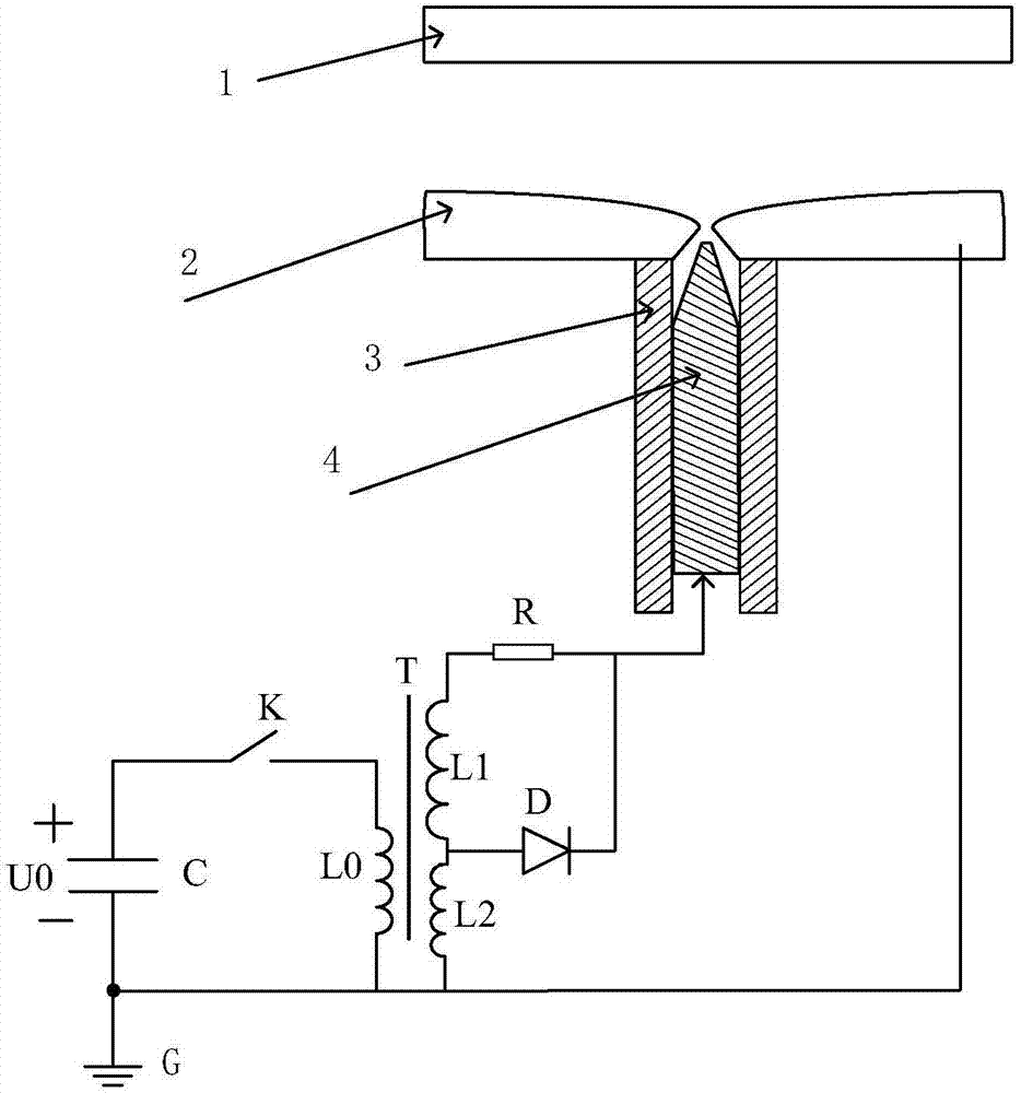
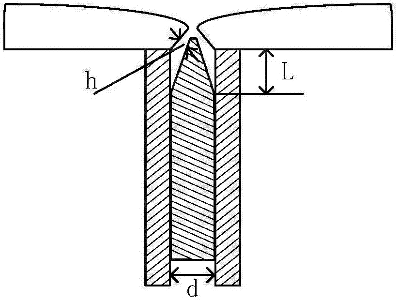
The invention discloses a plasma injection switch device. The plasma injection switch device comprises a first main electrode, a second main electrode, an insulating ring, a trigger pin electrode and a trigger circuit. The first main electrode is a planar electrode or a semispherical electrode. The second main electrode is an inwards-concave curved-surface electrode. The trigger pin electrode is covered with the insulating ring. A plasma injection cavity is formed by the insulating ring, the trigger pin electrode and the second main electrode jointly. A nozzle opening of the plasma injection cavity is located in the middle or center of the second main electrode. The trigger pin electrode is in a long and thin conical surface pin head shape. The trigger circuit is of a double-secondary-winding pulse transformer structure. Through the structure of the curved-surface main electrode, the center of the electrode can be prevented from being excessively ablated, blockage of a nozzle and accumulation of ablated materials in the center are avoided, and the service life of a plasma injection switch is prolonged. Due to the trigger circuit, it can be guaranteed that trigger currents cannot be rapidly attenuated, more abundant plasma can be formed, and the injection height of the plasma is increased.

Description

technical field [0001] The invention belongs to the technical fields of high-voltage electrical appliances and pulse power, and relates to a plasma jet switch device. Background technique [0002] In the past two years, in order to solve the problem of reliable triggering of gas spark switches under extremely low operating coefficients, China's Tie Weihao, Liu Shanhong and others proposed the jet plasma triggering technology. This gas spark switch is based on the traditional three-electrode field-distorted gas switch structure, and a plasma injection cavity consisting of an electrode plate, an insulating ring and a needle electrode is embedded inside the trigger electrode. A spark discharge inside the injection chamber is induced by applying a trigger pulse, generating a large number of charged particles. At the same time, the heat generated by the discharge heats the gas in the injection chamber, and the discharge ablates the insulating material to generate a large amount ...

Claims


Application Information

Patent Timeline
Patent Type & Authority Patents(China)
IPC IPC(8): H05H1/26
CPCH05H1/26
Inventor 李黎程勇彭明洋潘垣
Owner HUAZHONG UNIV OF SCI & TECH
Learn More