Eureka AIR delivers breakthrough ideas for toughest innovation challenges, trusted by R&D personnel around the world.

Method for designing cutting conditions for cutting

A technology of cutting processing and cutting conditions, applied in the design field of cutting conditions, can solve problems such as impractical, unrealistic, and energy-consuming, and achieve the effect of easy design and vibration prevention

Active Publication Date: 2016-08-17
KOBE STEEL LTD
View PDF8 Cites 2 Cited by
  • Summary
  • Abstract
  • Description
  • Claims
  • Application Information

AI Technical Summary

Problems solved by technology

[0004] In addition, regarding the tool life of cutting tools, if the cutting process is not performed based on appropriate cutting conditions, the tool life will become extremely short.
However, it is difficult to accurately estimate the cutting conditions for extending the tool life, and in many cases, the cutting conditions (especially the cutting speed of the cutting tool) are designed with a margin
[0005] However, there is a concern that additional cutting costs will be incurred with regard to the above-mentioned cutting conditions with margins.
For example, there is a problem that the tool is replaced before the tool life of the cutting tool is reached, or cutting time is wasted due to low-load cutting conditions
However, when designing cutting conditions, there are many calculations and condition items, and it takes effort to obtain cutting conditions, so it is not realistic.
[0018] In short, it is not practical to use the techniques of Non-Patent Document 1 and Non-Patent Document 2 to design appropriate cutting conditions in the actual cutting process.

Method used

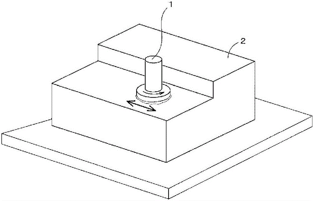
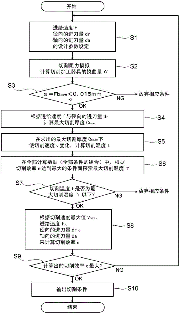
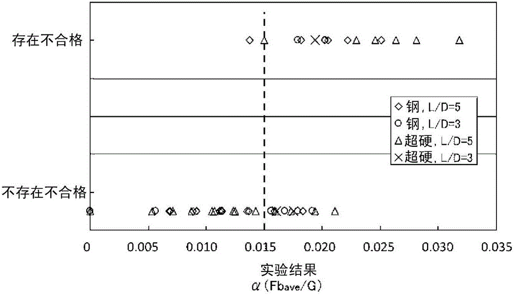

Image

  • Method for designing cutting conditions for cutting
  • Method for designing cutting conditions for cutting
  • Method for designing cutting conditions for cutting

Examples


experiment example

[0105] Next, using the method of designing cutting conditions in cutting according to the present invention, experimental results in which cutting conditions are designed will be described.

[0106] As the cutting tool 1 used in this experiment, an end mill tool with a tool diameter of 30 mm, a cutting edge of R0.8 mm, four blades, and a protrusion length of 150 mm was prepared, and as the workpiece 2, S45C carbon steel was prepared. (Carbon steel for machine structure: JIS G 4051 (1979)). Then, an experiment was performed on design of cutting conditions and optimization of cutting conditions when cutting S45C carbon steel, which is the workpiece 2, using the above-mentioned end mill tool 1 .

[0107] As a result of applying the design method of cutting conditions, it is calculated that the feed rate f of the end mill tool 1 is 197 mm / min, the radial feed amount dr is 7.5 mm, and the axial feed amount da is 102 mm. The speed is 4918rpm, and the twist angle is 60 degrees.

[...


PUM


Abstract

Design parameters of a cutting tool (1), which include the feed speed (f), the cutting depth (da) in an axial direction, the cutting depth (dr) in a radial direction, and the cutting speed (v), are used to calculate the deflection amount (alpha) of the cutting tool (1). It is determined whether chatter vibration of the cutting tool (1) will occur, on the basis of the deflection amount (alpha) and a prescribed threshold value (beta), and the maximum cutting thickness (Ctmax) is calculated on the basis of the determination result. The cutting temperature (t) is calculated from the maximum cutting thickness (Ctmax) and the cutting speed (v), and it is determined whether the tool life will be fulfilled, on the basis of the cutting temperature (t) and a prescribed threshold value (gamma). The cutting efficiency (e) is calculated on the basis of the determination result, and the calculated cutting efficiency (e) is compared with previously stored cutting-efficiency data, and, in cases when the calculated cutting efficiency (e) is the maximum value in the data, the design parameters are set as cutting conditions.

Description

technical field [0001] The invention relates to a design method of cutting conditions in cutting processing. Background technique [0002] In the past, when using cutting tools such as end mills and milling cutters to perform cutting processes such as turning and milling on steel and other workpieces, the feed rate of the cutting tool and the feed rate of the cutting tool Cutting is performed on the basis that the "cutting conditions" such as the amount of cutting tool, the cutting speed of the cutting tool, and the shape of the cutting tool are appropriate. [0003] However, when cutting with an end mill or a milling cutter, chatter may occur during cutting or the shape of the cutting tool may be deformed depending on the shape of the cutting tool. If such chatter vibration occurs, serious problems will arise regarding the machining accuracy and the properties of the machined surface of the material to be machined. Therefore, the operator who designs the cutting condition...

Claims


Application Information

Patent Timeline
Patent Type & Authority Applications(China)
IPC IPC(8): B23C1/00B23Q15/00G05B19/18
CPCB23C3/00G05B2219/36284G05B2219/41109B23Q15/18G05B19/40937G05B2219/36289G05B2219/41256G05B2219/37434G05B2219/50041Y02P90/02G05B19/4166G05B19/4163
Inventor 赤泽浩一浅井新辅坂本由介
Owner KOBE STEEL LTD
Why Eureka
Eureka Blog
Learn More