Method and device for the examination of a sample using optical projection tomography

一种光学投影断层、断层扫描的技术,应用在光学、光学元件、通过光学手段进行材料分析等方向,能够解决昂贵、显微镜无法灵活使用、麻烦等问题

Active Publication Date: 2016-08-17
LEICA MICROSYSTEMS CMS GMBH
View PDF7 Cites 7 Cited by
  • Summary
  • Abstract
  • Description
  • Claims
  • Application Information

AI Technical Summary

Problems solved by technology

On the downside, the microscope has a very complex structure; in particular, three objective lenses precisely aligned with each other are required simultaneously in order to focus the illumination light onto the sample and to receive the detection light emerging from the sample for the corresponding detectors
In addition, the microscope cannot be used flexibly
For example, the sample must forcibly move relative to the microscope so that a three-dimensional image of the sample can be generated; this is cumbersome and not possible for every type of sample because the experimental space is limited by the three objectives
Furthermore, it is not possible, or at best only difficult possibilities, to implement such microscopes in conventional microscope configurations (in particular using conventional microscope stands), which makes the manufacture of such microscopes complex and expensive

Method used


Image

  • Method and device for the examination of a sample using optical projection tomography
  • Method and device for the examination of a sample using optical projection tomography
  • Method and device for the examination of a sample using optical projection tomography

Examples


Embodiment Construction

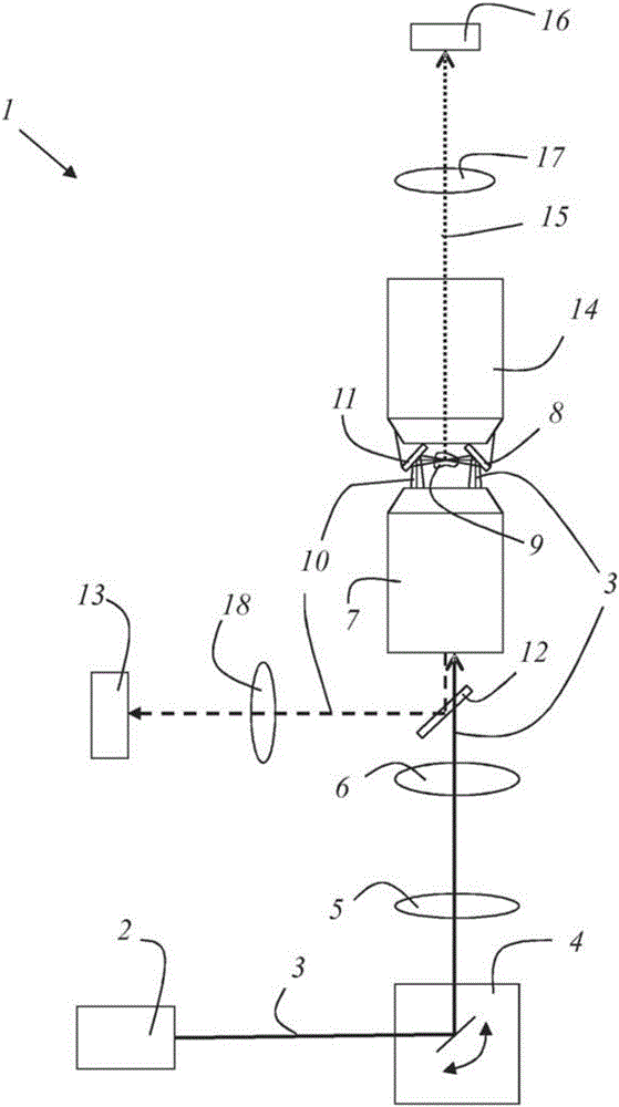
[0046] figure 1 An exemplary embodiment of a device 1 according to the invention is shown. The device comprises a light source 2 which may in particular be embodied as a laser. The light source 2 emits an illumination beam 3 which is deflected by a beam deflection device 4 which is adjustable for the deflection angle. After deflection, the illumination beam 3 travels through the scan lens 5 and the tube lens 6 , through the beam splitter 12 , and to the objective lens 7 which focuses the illumination beam 3 .

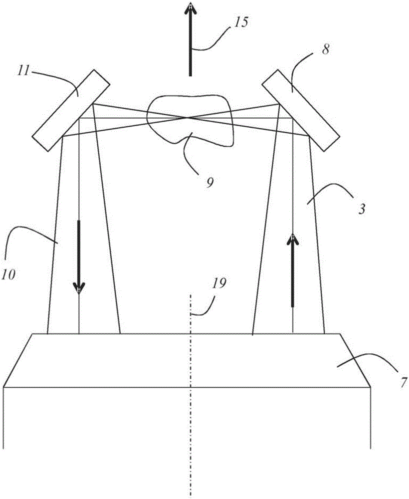
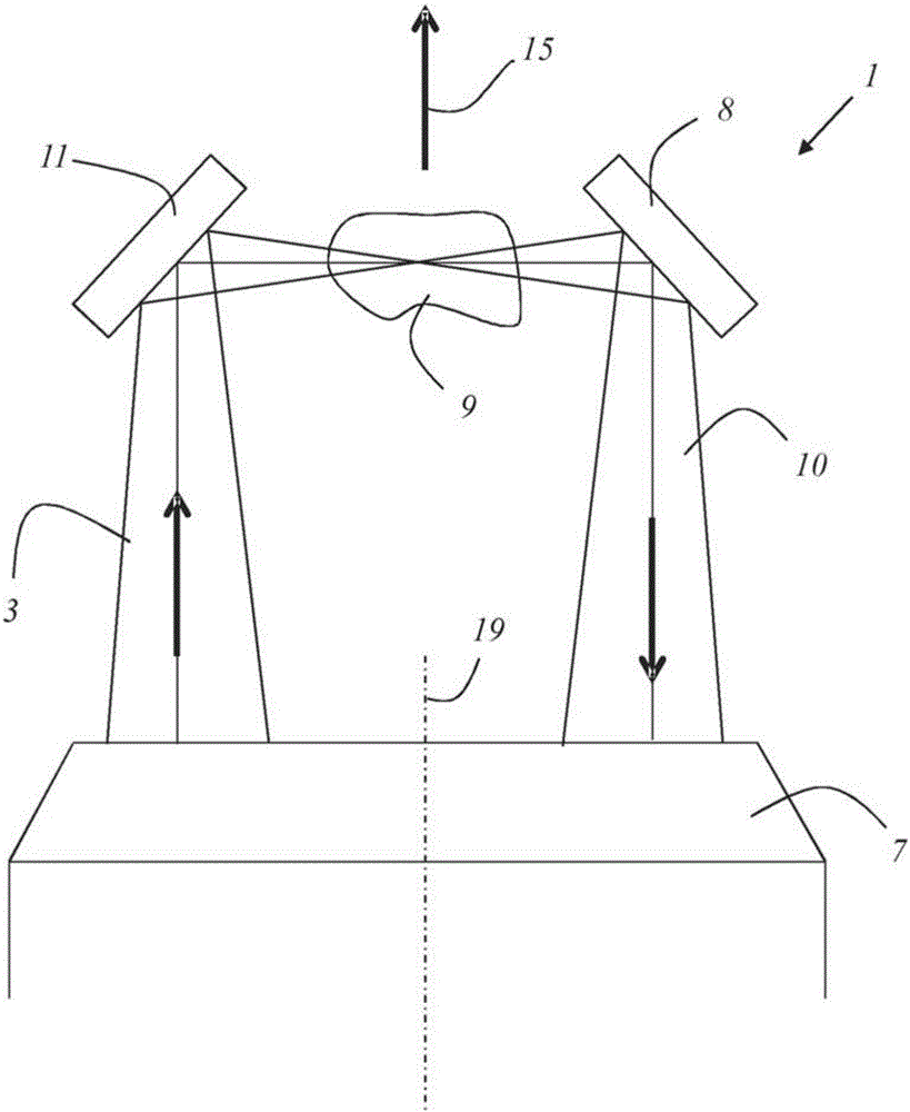
[0047] The beam deflecting device 4 is adjusted in such a way that the illuminating beam 3 passes through the objective pupil of the objective 7 at an inclination relative to the optical axis, so that it leaves the objective 7 eccentrically, i.e. with a transverse deviation relative to the optical axis of the objective 7 and then incident on the illumination light deflecting part 8, which deflects the illumination beam 3 to the sample preferably by about 90 degrees. ...


PUM


Abstract

The invention relates to a method for the examination by tomography of a sample (9). According to said method, a sample (9) is illuminated with an illumination light beam (3), and a transmission light beam (10), which contains the light of the illumination light beam (3) transmitted through the sample (9), is detected by means of a transmission detector (13). The invention further relates to a device for the examination of a sample (9) by tomography. The illumination light beam (3) and the transmission light beam (10) pass through the same lens (7) with opposite propagation directions.

Description

technical field [0001] The invention relates to a method for the tomographic investigation of a sample, in which method the sample is irradiated with an illumination beam and in which a transmitted beam comprising light transmitted through the sample of the illumination beam is detected with a transmission detector. [0002] The invention furthermore relates to a device for the tomographic investigation of a sample, which device has a light source for generating an illumination beam irradiating the sample to be investigated, and a device for detecting a transmitted beam of the illumination beam containing light transmitted through the sample transmission detector. Background technique [0003] WO 2012 / 027542 A2 discloses a microscope that simultaneously allows both optical tomographic and SPIM studies of samples. This document specifically describes optical projection tomography (OPT). Disadvantageously, the microscope has a very complex structure; in particular, three obj...

Claims


Application Information

Patent Timeline
Patent Type & Authority Applications(China)
IPC IPC(8): G01N21/47G02B21/00G01N21/64
CPCG01N21/4795G01N21/6458G01N2021/6491G02B21/088G01N21/47G01N21/59G01N2201/06113G01N2201/0636G01N2201/10G02B21/0028
Inventor W·克内贝尔W·福格F·希克曼
Owner LEICA MICROSYSTEMS CMS GMBH
Why Eureka
Try Eureka