Hip joint prosthesis part

A hip joint prosthesis and component technology, applied in hip joints, joint implants, joint implants and other directions, can solve the problem of not being able to have good bone fusion performance and friction performance at the same time, achieve good friction performance and meet demand Effect

Active Publication Date: 2016-08-24
BEIJING AKEC MEDICAL
View PDF10 Cites 6 Cited by
  • Summary
  • Abstract
  • Description
  • Claims
  • Application Information

AI Technical Summary

Problems solved by technology

[0003] The main purpose of the present invention is to provide a hip joint prosthesis to solve the problem that the hi

Method used


Image

  • Hip joint prosthesis part
  • Hip joint prosthesis part
  • Hip joint prosthesis part

Examples


Embodiment Construction

[0025] It should be noted that, in the case of no conflict, the embodiments in the present application and the features in the embodiments can be combined with each other. The present invention will be described in detail below with reference to the accompanying drawings and examples.

[0026] It should be pointed out that the following detailed description is exemplary and intended to provide further explanation to the present application. Unless defined otherwise, all technical and scientific terms used herein have the same meaning as commonly understood by one of ordinary skill in the art to which this application belongs.

[0027] It should be noted that the terminology used here is only for describing specific implementations, and is not intended to limit the exemplary implementations according to the present application. As used herein, unless the context clearly dictates otherwise, the singular is intended to include the plural, and it should also be understood that wh...


PUM


Abstract

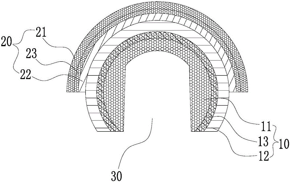
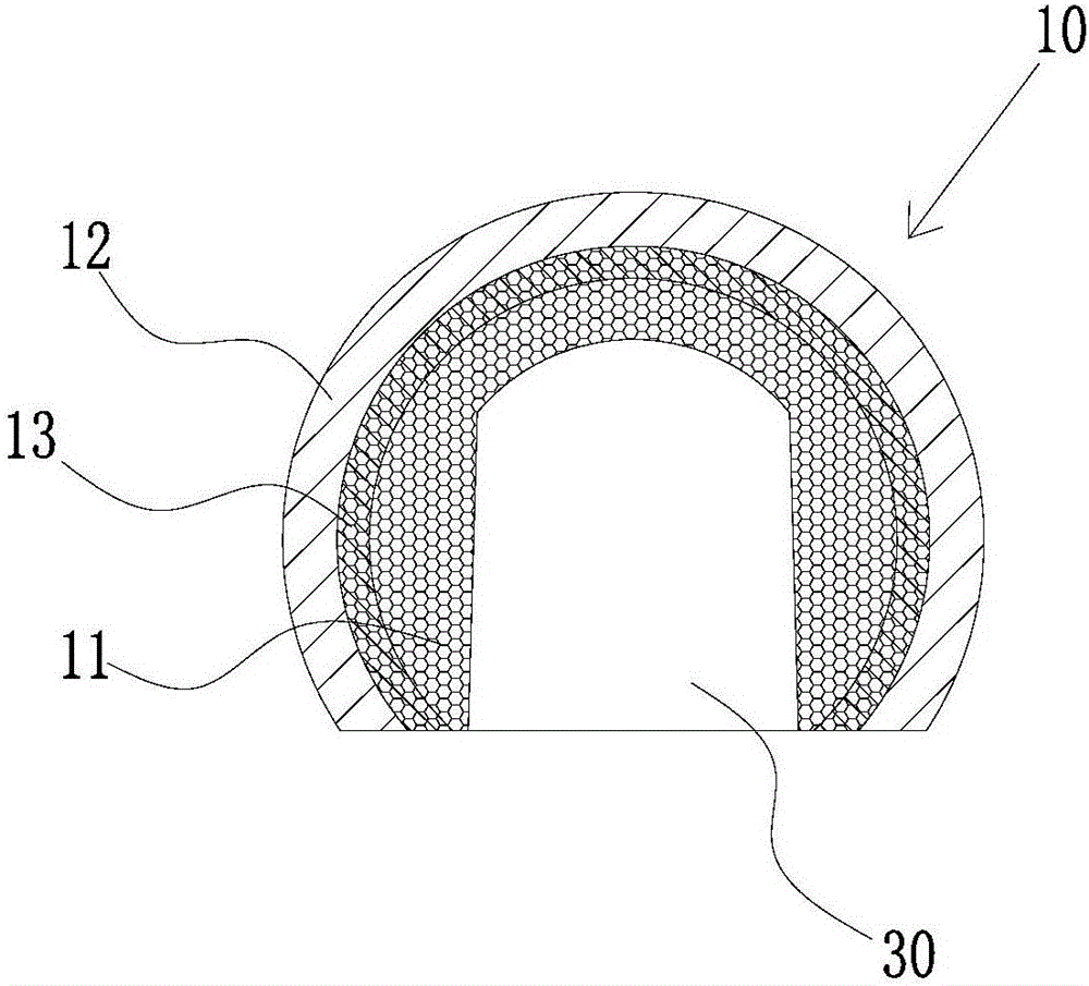
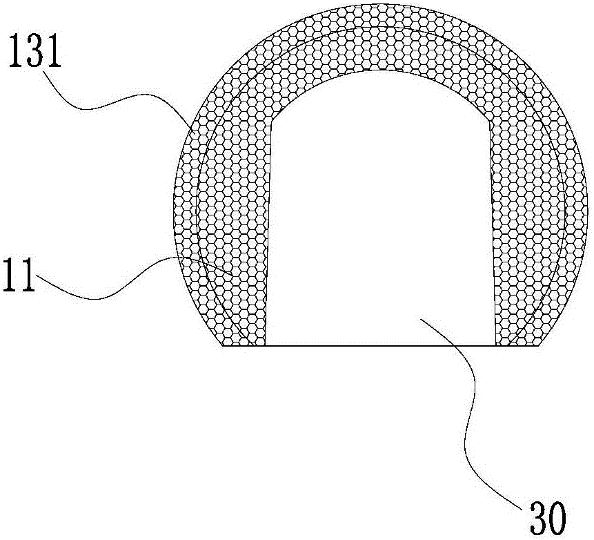
The invention provides a hip joint prosthesis part. The hip joint prosthesis part comprises femoral head prosthesis part and an acetabular cup prosthesis part, wherein the femoral head prosthesis part comprises a first porous layer, a first metal entity layer arranged on one side of the first porous layer and a first cladding layer formed between the first porous layer and the first metal entity layer through the first cladding technology, and a first smooth surface is formed on the surface, away from the first cladding layer, of the first metal entity layer; the acetabular cup prosthesis part comprises a second porous layer, a second metal entity layer arranged on one side of the second porous layer and a second cladding layer formed between the second porous layer and the second metal entity layer through the second cladding technology, a second smooth surface is formed on the surface, away from the second cladding layer, of the second metal entity layer, and the first smooth surface is matched with the second smooth surface. By the hip joint prosthesis part, the problem that an existing hip joint prosthesis part cannot have both good bone fusion performance and good friction performance at the same time in the prior art can be solved effectively.

Description

technical field [0001] The invention relates to the technical field of medical devices, in particular to a hip joint prosthesis component. Background technique [0002] At present, in the manufacture of medical implants, it is often encountered that there are different material requirements for different parts of a product. For example, for femoral head necrosis, the current common treatment method is to perform hip replacement surgery, cut the necrotic femoral head and femoral neck from the greater trochanter to the lesser trochanter, and then implant artificial acetabular cup prosthesis and artificial femur Bone prosthesis, and the above-mentioned artificial acetabular cup prosthesis and artificial femoral head prosthesis need to be able to form good bone fusion with human bone tissue and have excellent friction characteristics at the same time, but these two characteristics are difficult to combine on the same product reflect. In the prior art, porous bio-ceramics or po...

Claims


Application Information

Patent Timeline
IPC IPC(8): A61F2/32
CPCA61F2/32
Inventor 张卫平
Owner BEIJING AKEC MEDICAL
Why Eureka
Try Eureka