Auxiliary device of combined lower limb orthopedic operation traction bed
An orthopaedic surgery, auxiliary device technology, applied in the direction of surgery, operating table, medical science, etc., to achieve the effect of good traction effect
- Summary
- Abstract
- Description
- Claims
- Application Information
AI Technical Summary
Problems solved by technology
Method used
Image

Examples
Embodiment 1
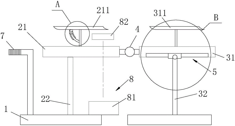
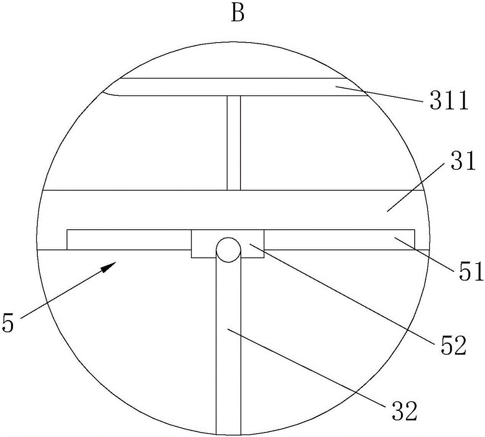
[0031] Embodiment one: if figure 1 , 2 , 3, the present embodiment includes a ground support structure 1, and the support assembly for one side of the affected leg is installed on the ground support structure 1. The support assembly can be one set or two sets, depending on the patient's injury situation. The support assembly includes a thigh support 21 erected on the ground support structure 1, and a thigh support 211 for placing the thighs is also erected on the thigh support 21; a thigh support unit 22 is also installed between the thigh support 21 and the ground support structure 1 , the thigh support unit 22 is used to support the thigh support 21 . A calf support 31 is also erected on the ground support structure 1, and a calf support 311 for placing the calf is also erected on the calf support, and a hydraulic cylinder 32 is also installed between the calf support 31 and the ground support structure 1, and the hydraulic cylinder 32 is used for It supports the lower leg...
Embodiment 2
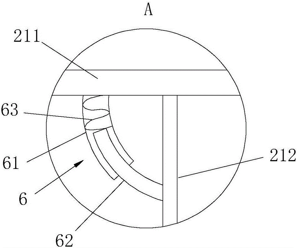
[0037] Embodiment two: if Figure 4 , 5 As shown, the difference from Embodiment 1 is that the top of the thigh bracket 211 and the bracket rod 212 are connected by a secondary universal joint 91, and a buffer limit unit 6 is also provided between the thigh bracket 211 and the bracket rod 212, The buffer limit unit 6 includes: an upper annular guide groove 92 set at the bottom of the thigh bracket 211 and centered on the auxiliary universal joint 91; The upper block 93 of sliding fit; the lower annular guide groove 94 provided on the side wall of the bracket rod 212 and arranged axially around the bracket rod 212; clamped in the lower annular guide groove 94 and connected with the lower annular guide groove 94 is a lower block 95 that slides and fits; the arc-shaped sleeve 61 and the arc-shaped rod 62 that are socketed and matched with each other, the arc-shaped sleeve 61 and the arc-shaped rod 62 are all arc tubes centered on the auxiliary universal joint 91 be placed in th...
Embodiment 3
[0038] Embodiment three: as Image 6 As shown, the difference from Embodiment 1 is that the lifting support unit is a hydraulic cylinder 32b, and one axial end (piston rod end) of the hydraulic cylinder 32b is hingedly matched with the bottom of the calf support 31, and the other axial end (cylinder body) of the hydraulic cylinder 32b is end) is hingedly fitted with the ground support structure 1. The effect of the hydraulic cylinder 32b is not only to realize the lifting of the calf support 31, but also to support the calf support 31, and cooperate with the calf support 31 to play a supporting role when it is connected with the universal joint part 4, so as to ensure the stability of the calf support 31 during work. Of course, the hydraulic cylinder 32b can also be replaced by telescopic elements with axial functions such as telescopic rods or cylinders, and these devices all have a locking function after axial telescopic expansion. In addition, the number of hydraulic cylin...
PUM
 Abstract
Description
Claims
Application Information
 - R&D
- Intellectual Property
- Life Sciences
- Materials
- Tech Scout
- Unparalleled Data Quality
- Higher Quality Content
- 60% Fewer Hallucinations
Browse by: Latest US Patents, China's latest patents, Technical Efficacy Thesaurus, Application Domain, Technology Topic, Popular Technical Reports.
© 2025 PatSnap. All rights reserved.Legal|Privacy policy|Modern Slavery Act Transparency Statement|Sitemap|About US| Contact US: help@patsnap.com