
Automatic glue throwing and filling device and method for filtering piece

A technology of filter parts and glue rejection, which is applied to the device and coating of the surface coating liquid, can solve the problems of motor overheating and burning, large glue feeding resistance, corrosion and other problems, and achieves extended service life, stable glue suction pressure, The effect of reducing the suction resistance

Active Publication Date: 2016-08-24
HUBEI HUAQIANG HIGH TECH CO LTD
View PDF4 Cites 15 Cited by
  • Summary
  • Abstract
  • Description
  • Claims
  • Application Information

AI Technical Summary

Problems solved by technology

[0002] At present, in the field of national defense technology, the glue filling device for canister filter parts is backward, and the glue pump adopts gear pump. The gear is easy to be polluted, corroded, and bonded after long-term contact with glue, resulting in excessive resistance to glue delivery and unstable glue output. A series of problems such as motor overheating and burning; and there is no suitable canister filter glue filling fixture, the canister filter glue filling seal quality and glue appearance quality are generally poor. For a long time, canister filter glue filling is a The technical bottleneck of the entire industry needs to be resolved urgently

Method used


Image

  • Automatic glue throwing and filling device and method for filtering piece
  • Automatic glue throwing and filling device and method for filtering piece

Examples


Embodiment 1

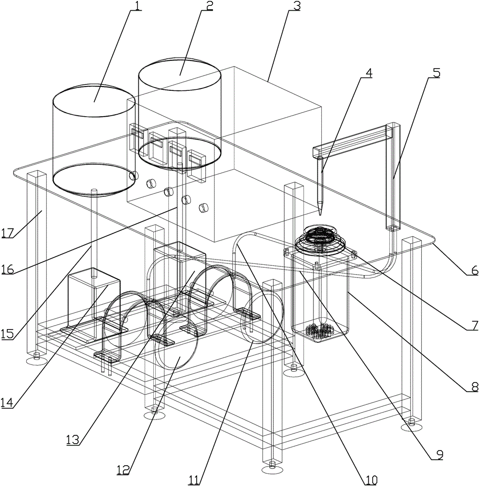
[0033] Such as Figure 1-2 As shown, the automatic glue pouring device for the filter element includes a workbench 6 fixedly installed on the top of the bracket 17, and a No. 1 glue tank 1 and a No. 2 glue tank are installed side by side on the left side of the workbench 6. Tank 2; a control box 3 is installed in the middle of the workbench 6.

[0034] Further, the bottom of the No. 1 plastic tank 1 is connected to the No. 1 buffer tank 14 through the No. 1 rubber inlet pipe 15, and the No. 1 buffer tank 14 is connected to the liquid suction port of the No. 1 vacuum pump 12. The No. 1 vacuum pump The drain port of 12 links to each other with No. 1 rubber outlet pipe 9.

[0035] Further, the bottom of the No. 2 rubber tank 2 is connected to the No. 2 buffer tank 13 through the No. 2 rubber inlet pipe 16, and the No. 2 buffer tank 13 is connected to the liquid suction port of the No. 2 vacuum pump 11. The No. 2 vacuum pump The drain port of 11 links to each other with No. 2 ru...

Embodiment 2

[0044] The tank glue method adopting the automatic glue throwing glue pouring device of the filter element, it comprises the following steps:

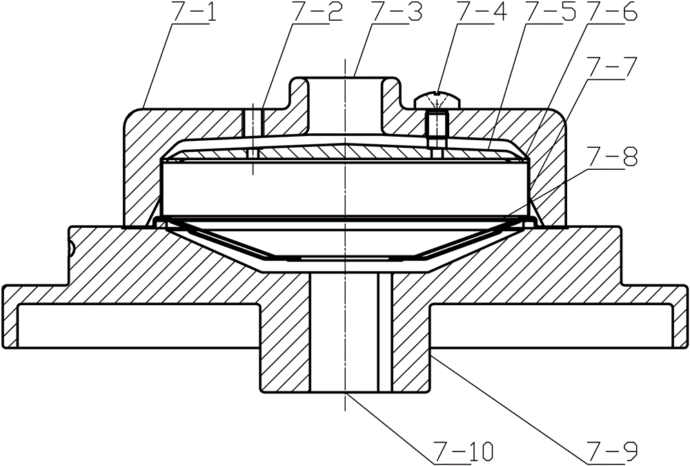
[0045] In the first step, put a certain amount of No. 1 rubber and No. 2 rubber in the No. 1 plastic tank 1 and No. 2 plastic tank 2 respectively, install the filter shell 7-7 on the base 7-9, and place the filter element 7 -8 is installed on the filter shell 7-7, and is fixed by pressing the cover 7-1, and then the whole tank glue fixture 7 is installed on the output shaft of the variable frequency motor 8 through the shaft hole 7-10;

[0046] In the second step, start the No. 1 vacuum pump 12 and the No. 2 vacuum pump 11, so that a certain negative pressure is formed inside the No. 1 buffer tank 14 and No. 2 buffer tank 13, and the No. 1 rubber is sequentially passed through the No. 1 rubber inlet pipe 15, No. 1 buffer tank 14, No. 1 vacuum pump 12, and No. 1 rubber outlet pipe 9 enter the mixer 4; No. No. rubber hose 10 enters mixe...


PUM


Abstract

The invention discloses an automatic glue throwing and filling device and method for a filtering piece, and belongs to automatic glue throwing and filling devices in the technical field of chemical defense. The automatic glue throwing and filling device mainly comprises accessories including a first glue tank, a second glue tank, a control box, a mixer, a mixer support, a working table, a glue filling clamp, a variable frequency motor, a first glue outlet tube, a second glue outlet tube, a second vacuum pump, a first vacuum pump, a second buffering tank, a first buffering tank, a first glue inlet tube, a second glue inlet tube, a connecting cable and the like. Multi-component glue can be mixed uniformly, and is automatically thrown into a narrow gap between the outer shell of the filtering piece and a filtering element for precision glue filling by the glue filling clamp which is designed specially, so that a surface, which is in contact with the filtering element, of the outer shell of the filtering piece is sealed completely, and quite high consistent sealing level and glue filling appearance quality are obtained.

Description

technical field [0001] The invention relates to a device and a method for automatically throwing glue and pouring glue into a filter element of a canister used in the field of chemical defense technology. The narrow gap between the canister filter shell and the filter element is precisely filled with glue. Background technique [0002] At present, in the field of national defense technology, the glue filling device for canister filters is backward, and the glue pump adopts a gear pump. The gear is easy to be polluted, corroded, and bonded after long-term contact with the glue, resulting in excessive resistance to glue delivery and unstable glue output. A series of problems such as motor overheating and burning; and there is no suitable canister filter glue filling fixture, the canister filter glue filling seal quality and glue appearance quality are generally poor. For a long time, canister filter glue filling is a The technical bottleneck of the entire industry needs to be...

Claims


Application Information

Patent Timeline
Patent Type & Authority Applications(China)
IPC IPC(8): B05C5/02B05C11/10
CPCB05C5/0208B05C11/1002Y02P70/10
Inventor 李方罗张斌杜凯刘兰同韩文韬黄娟
Owner HUBEI HUAQIANG HIGH TECH CO LTD
Learn More