
Belt conveyor with linear detector

A belt conveyor and detector technology, which is used in conveyor objects, conveyor control devices, transportation and packaging, etc., can solve the problem of limited space for temperature measurement optical cables, reduce the working distance of detection optical fibers, and cannot directly detect the roller temperature. and other problems, to achieve the effect of high reliability, fast real-time response, and low false alarm rate

Inactive Publication Date: 2016-08-24
谭刚
View PDF4 Cites 1 Cited by
  • Summary
  • Abstract
  • Description
  • Claims
  • Application Information

AI Technical Summary

Problems solved by technology

[0010] In the above technical solutions, the temperature measuring optical cable is mainly installed on the roller bracket or the truss channel steel. Their disadvantage is that they cannot directly detect the temperature of the idler roller, but indirectly detect the temperature of the roller bracket or the farther truss channel steel.
The inability to directly measure temperature is the shortcoming of these technical solutions
[0011] In addition, the existing technology has limited space for installing temperature measurement optical cables. In order to obtain normal measurement results, it is often necessary to coil a certain length of optical cables and stuff them into roller brackets or protective containers.
This kind of coiling with many turns and small bending radius will greatly increase the additional loss of the optical fiber and seriously reduce the actual working distance of the detection optical fiber

Method used


Image

  • Belt conveyor with linear detector
  • Belt conveyor with linear detector
  • Belt conveyor with linear detector

Examples


Embodiment 1

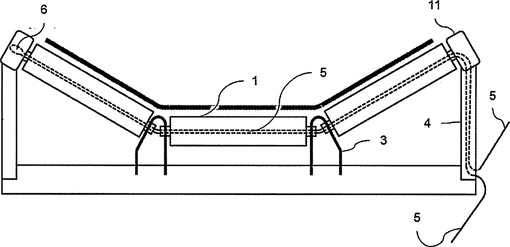
[0031] Refer to attached figure 1 And attached figure 2 , a realization scheme of a belt conveyor with a temperature-measuring optical cable is given:

[0032] The shaft 2 of the idler 1 is inserted into the groove on the idler bracket 3 and the idler support 4 through the flat groove on it; the shaft 2 is made of 45 seamless steel pipes through turning, milling, heat treatment and other processes , inner diameter 20mm, outer diameter 30mm.

[0033] The linear detector 5 is an optical cable with a built-in multimode optical fiber (including the outer diameter of the coating layer of 600 microns), spiral steel wire armor, the tensile part is aramid fiber, the outer sheath is flame-retardant plastic, and the outer diameter is 2.2mm , the instantaneous minimum bending radius is 6mm, and the short-term allowable tensile force is 200kN; after the optical cable passes through the channel of the shaft of a trough-shaped idler group in turn, it turns back according to the original ...

Embodiment 2

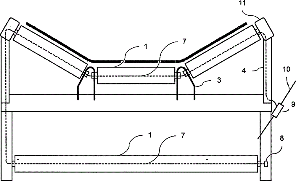
[0038] Refer to attached image 3 , a realization scheme of a belt conveyor with a branch-type temperature-sensing cable is given:

[0039] The shaft 2 of the idler 1 is inserted into the groove on the idler bracket 3 and the idler support 4 through the flat groove on it; the shaft 2 is made of 20-gauge steel seamless steel pipe through turning, milling, heat treatment and other processes , inner diameter 10mm, outer diameter 25mm.

[0040]The linear detector 7 is a temperature-sensing cable branch line, double-core switch type, armored, and the outer sheath is flame-retardant plastic, with an outer diameter of 4.6mm; the temperature-sensing cable branch line passes through the shaft channel of a trough-shaped idler group in turn , and continue down the roller strut and pass through the channel of the shaft of a horizontal roller, forming a blind end at the other end of the channel and protected by a terminal piece 8. The temperature-sensing cable branch line is a branch whe...


PUM

PropertyMeasurementUnit
Bending radiusaaaaaaaaaa

Abstract

The invention relates to a belt conveyor, in particular to a belt conveyor with a linear detector. The belt conveyor comprises support rollers and the linear detector. A shaft of each support roller is tubular. Each support roller is provided with a channel penetrating in the axial direction. The linear detector is arranged in the channels. In this way, the linear detector can directly detect the temperature or other state quantities of the support rollers.

Description

technical field [0001] The invention relates to a belt conveyor, in particular to a belt conveyor with a linear detector. Background technique [0002] Belt conveyor is an important transportation equipment in metallurgy, mining, power, building materials, transportation and other industries. During its operation, many factors will cause slippage between the belt and the idler roller, which will cause the surface temperature of the roller to rise rapidly, forming a fire hazard. Due to the long distance of the belt conveyor and the large number of rollers, manual inspection is difficult, and conventional point detectors are not suitable. At present, the latest monitoring method adopts linear temperature-sensitive detectors. [0003] These new linear temperature detectors mainly include distributed optical fiber temperature sensors, temperature sensing cables, etc. Distributed optical fiber temperature sensor has at least four implementation technologies: ROTDR based on Ram...

Claims


Application Information

Patent Timeline
IPC IPC(8): B65G39/12B65G43/00
Inventor 谭刚
Owner 谭刚
Learn More