Clamp for clamping workpieces

A workpiece clamping and workpiece technology, applied in the field of magnetron sputtering coating, can solve the problem that different types of workpieces cannot be clamped at the same time

Inactive Publication Date: 2016-08-24
CHENGDU CVAC VACUUM TECH CO LTD
View PDF6 Cites 3 Cited by
  • Summary
  • Abstract
  • Description
  • Claims
  • Application Information

AI Technical Summary

Problems solved by technology

[0008] The invention provides a workpiece clamping fixture to solve the technical proble

Method used


Image

  • Clamp for clamping workpieces
  • Clamp for clamping workpieces
  • Clamp for clamping workpieces

Examples


Embodiment Construction

[0035] In order to enable those skilled in the technical field to which the application belongs to understand the application more clearly, the technical solutions of the application will be described in detail below through specific embodiments in conjunction with the accompanying drawings.

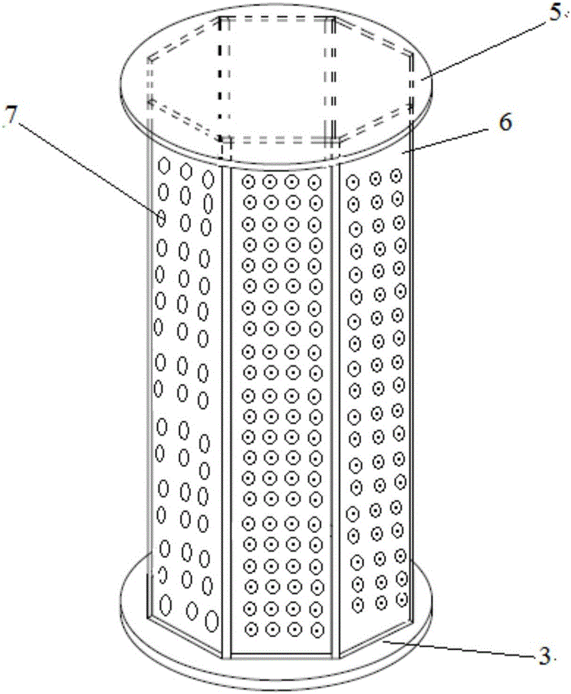
[0036] In an embodiment of the present invention, a workpiece clamping fixture is disclosed, which is mainly used for clamping a workpiece, such as a substrate to be coated. Of course, the workpiece can also be a special-shaped workpiece, and the special-shaped workpiece refers to a workpiece with an irregular shape, such as a hemispherical substrate to be coated.

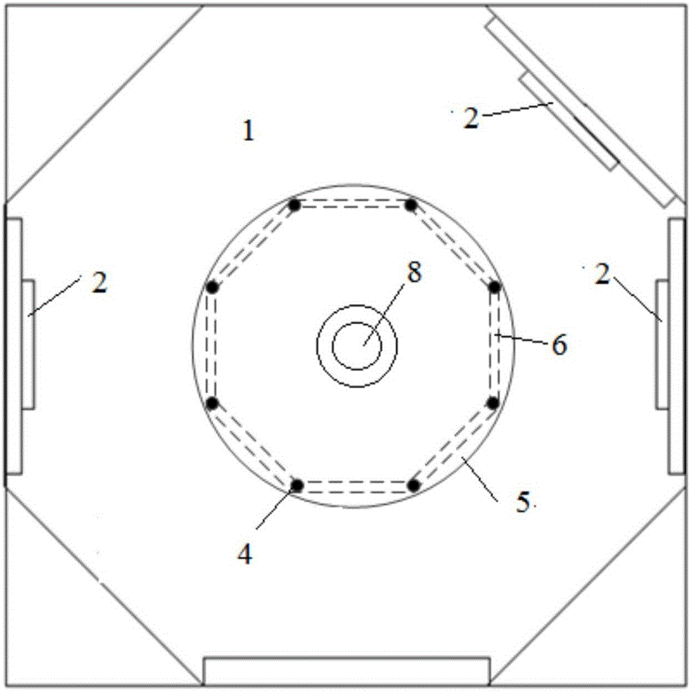
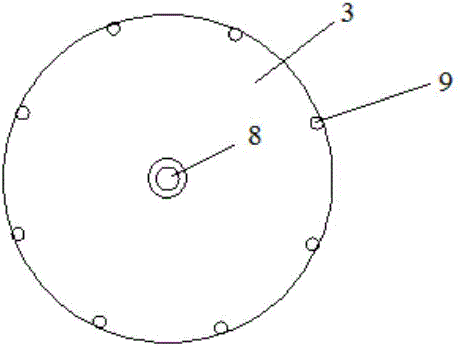
[0037] See below Figure 1-Figure 2 , is a structural schematic diagram of the workpiece clamping fixture of the present invention.

[0038] A target 2 is arranged on the side wall of the sputtering chamber 1, and the workpiece clamping fixture is located in the cavity center of the sputtering chamber 1, and the distance bet...


PUM


Abstract

The invention discloses a clamp for clamping workpieces. The clamp comprises a base positioned at the chamber bottom of a sputtering chamber, stationary shafts on the base, workpiece clamping plates positioned between adjacent two stationary shafts, workpiece clamping holes formed in the workpiece clamping plates and a transmission shaft positioned between the base and the chamber bottom of the sputtering chamber. As at least two different types of workpieces can be simultaneously clamped by the workpiece clamping holes in each workpiece clamping plate, different types of workpieces can be simultaneously sputtered, and the sputtering efficiency is improved.

Description

technical field [0001] The present application relates to the technical field of magnetron sputtering coating, in particular to a workpiece clamping fixture. Background technique [0002] With the continuous improvement of people's living standards, more and more coating products are widely used, and the manufacture of corresponding vacuum coating equipment is becoming more and more important in the improvement of coating technology. Magnetron sputtering coating is one of the widely used coating technologies. Its principle is to use electrons to collide with the sputtering gas argon during the process of accelerating and flying to the substrate under the action of an electric field, and ionize a large number of argon ions and electrons. , the electrons fly to the substrate film, and continuously collide with the argon atoms in the process, generating more argon atoms and electrons; the argon ions are accelerated to bombard the target under the action of the electric field, s...

Claims


Application Information

Patent Timeline
IPC IPC(8): C23C14/50C23C14/35
CPCC23C14/35C23C14/505
Inventor 徐子明傅绍英向勇胡杨
Owner CHENGDU CVAC VACUUM TECH CO LTD
Why Eureka
Try Eureka