Sputtering target-backing plate assembly, and its production method

a technology of target backing plate and assembly method, which is applied in the direction of diaphragms, metal-working apparatus, metallic material coating process, etc., can solve the problems of strength and cooling power of the backing plate itself, and the bonding strength between the backing plate, so as to improve the bonding strength and improve the sputtering efficiency

Active Publication Date: 2015-06-23
JX NIPPON MINING & METALS CORP
View PDF22 Cites 3 Cited by
  • Summary
  • Abstract
  • Description
  • Claims
  • Application Information

AI Technical Summary

Benefits of technology

[0015]An object of the present invention is to provide a sputtering target-backing plate assembly that is used when magnesium (Mg) is the sputtering target material, and to resolve problems inherent in magnesium (Mg) and problems related to the selection of a backing plate to be compatible with magnesium by improving the bonding strength between the target and the backing plate in order to improve the sputtering efficiency.Technical Solution
[0037]When preparing a sputtering target-backing plate assembly by bonding a target material of Mg to a backing plate of Cu—Cr alloy, in the present invention, the target material is bonded to the backing plate via a layer of Ni or an alloy comprising Ni as a main component at the interface therebetween. The present invention thereby yields superior effects to increase the bonding strength, enable high-power sputtering, and improve the production efficiency.

Problems solved by technology

A target is usually bonded to a backing plate and subject to high-power sputtering in order to improve the production efficiency, but the problems resulting from such high-power sputtering are the strength and cooling power of the backing plate itself, and the bonding strength between the backing plate and the target.

Method used


Image

  • Sputtering target-backing plate assembly, and its production method
  • Sputtering target-backing plate assembly, and its production method
  • Sputtering target-backing plate assembly, and its production method

Examples


example 1

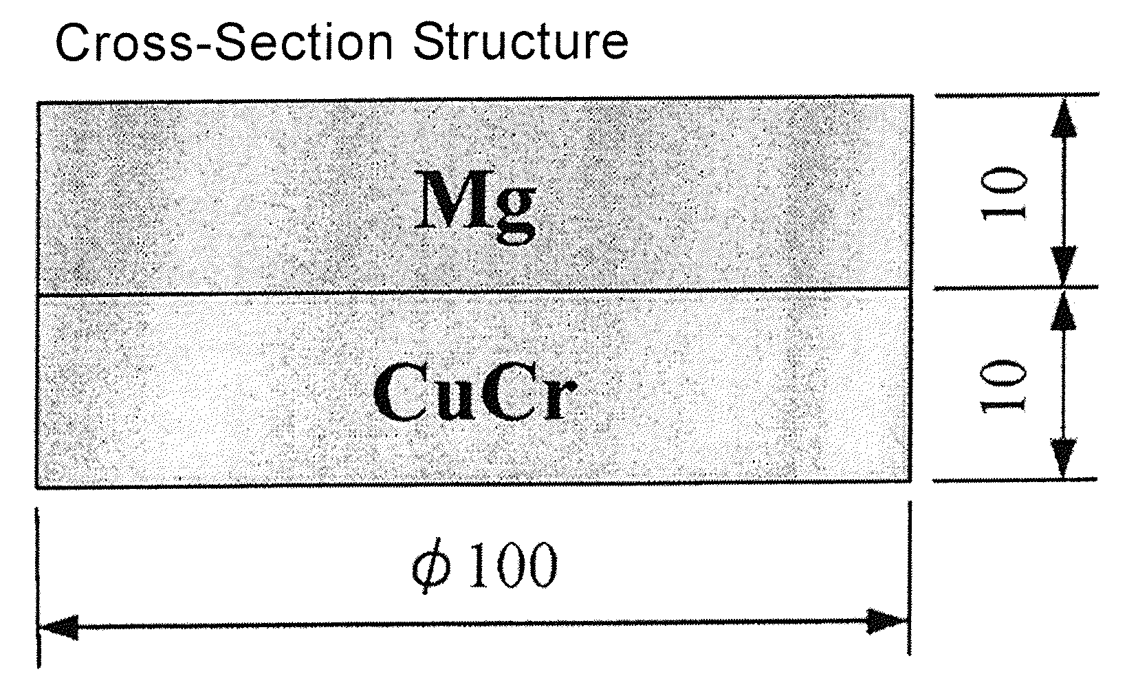
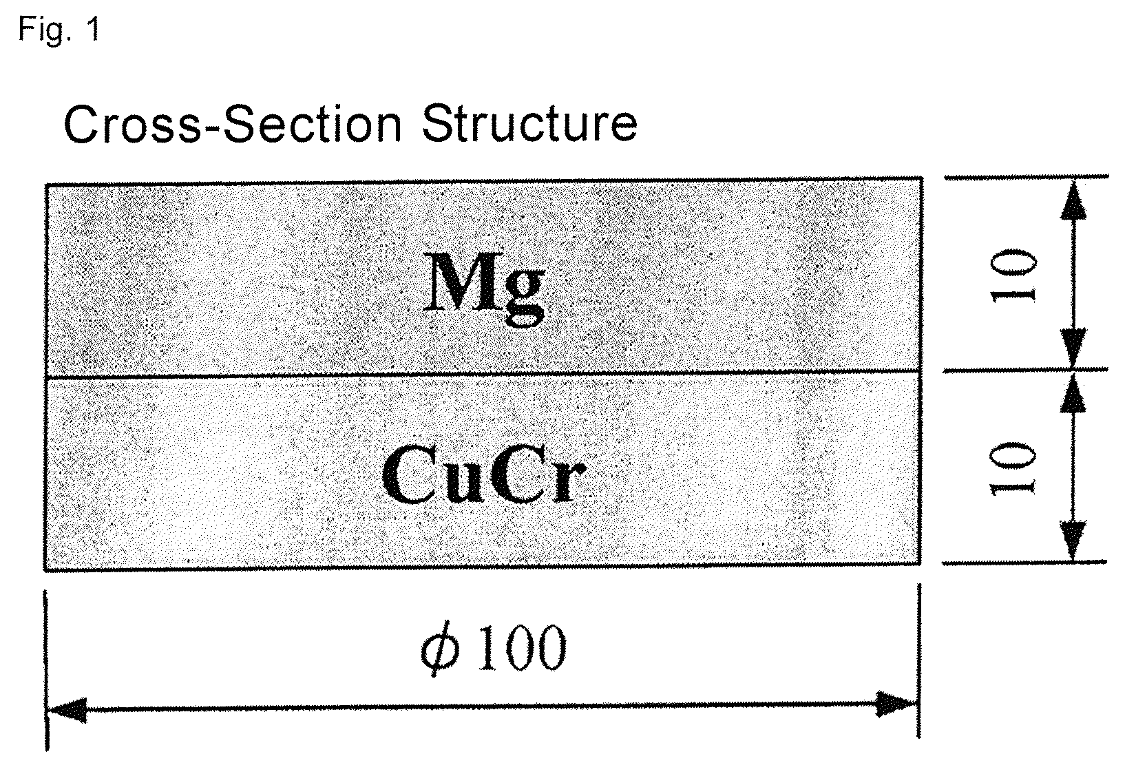
[0080]Example 1 is now explained. The target material (thickness of 10 mm, 100 mmφ) of high-purity magnesium of 5N (99.999 wt % excluding gas components) was used as a test piece. The Cu—Cr alloy (thickness 8 mm, 100 mmφ) having the foregoing composition was used as a backing plate. In addition, a Ni coating layer having a thickness of 0.1 μm was formed on the entire area of the bonding surface on the Mg target side by subjecting Ni to vapor deposition to obtain the test piece of Example 1.The conceptual diagram of this test piece is shown in FIG. 6.

[0081]After cleaning the surface of the target and the backing plate, these were vacuum-sealed in a SUS foil, and subject to HIP at a temperature of 290° C., pressure of 1450 kg / cm2, and holding time of 1 hour.

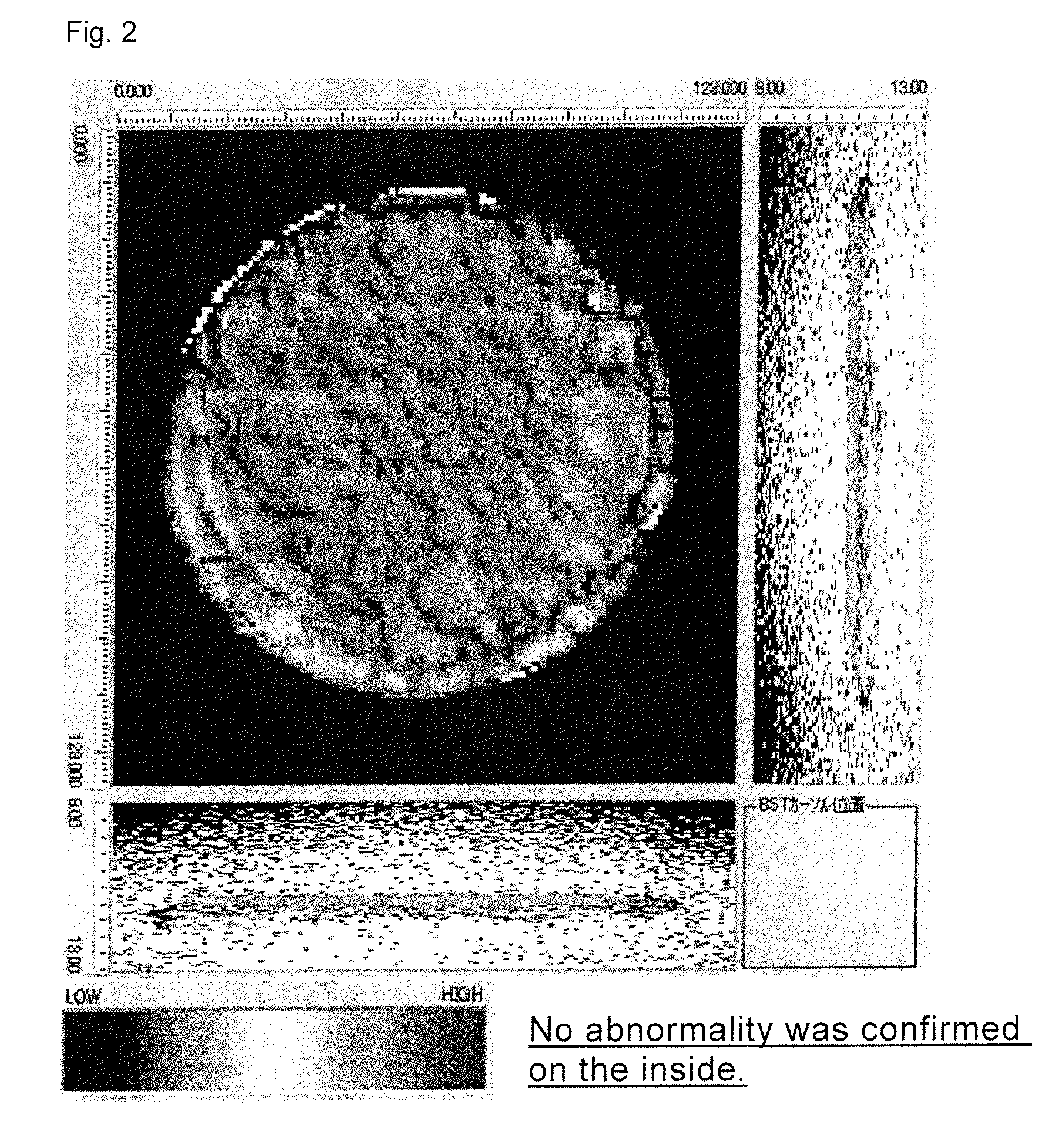
[0082]After bonding the target to the backing plate by interposing the Ni vapor-deposited layer at the interface therebetween, ultrasonic inspection was performed from the target side to observe the internal defects. In this ultras...

example 2

[0090]A test piece of the sputtering target-backing plate assembly was prepared as with the above by subjecting the bonding surface of the Cu—Cr alloy to crude processing using a lathe, and the same tests were performed thereto.

[0091]Consequently, it was confirmed that the bonding strength between the target and the backing plate had further increased. Although the improvement of the bonding strength depended on the shape and quantity thereof, an improvement of roughly 10 to 50% in the bonding strength was confirmed.

[0092]Subsequently, the interfacial observation was conducted as to the sputtering target-backing plate assembly. The results of observing the interface are shown in FIG. 10. One location from the central part, two locations from the ½R part, and two locations from the outer periphery were sampled, and, as shown in FIG. 10, no abnormality could be acknowledged at the interface between the Mg target and the Cu—Cr alloy backing plate.

[0093]The sputtering target-backing pla...


PUM

PropertyMeasurementUnit
thicknessaaaaaaaaaa
thicknessaaaaaaaaaa
tensile strengthaaaaaaaaaa

Abstract

A sputtering target-backing plate assembly obtained by bonding a target material of Mg to a backing plate of Cu—Cr alloy, wherein the target material and the backing plate are bonded via a layer of Ni or an alloy comprising Ni as a main component at the interface therebetween. An object of the present invention is to provide a sputtering target-backing plate assembly that is used when magnesium (Mg) is the sputtering target material, and to resolve problems inherent in magnesium (Mg) and problems related to the selection of a backing plate to be compatible with magnesium by improving the bonding strength between the target and the backing plate in order to improve the sputtering efficiency.

Description

BACKGROUND[0001]The present invention relates to a sputtering target-backing plate assembly that is used when magnesium (Mg) is the sputtering target material, and particularly relates to a sputtering target-backing plate assembly in which the bonding strength between the target and the backing plate has been increased in order to improve the sputtering efficiency, as well as to a method of producing the same.[0002]In recent years, a magnesium (Mg) sputtering target is required for use in MRAM. A target is usually bonded to a backing plate and subject to high-power sputtering in order to improve the production efficiency, but the problems resulting from such high-power sputtering are the strength and cooling power of the backing plate itself, and the bonding strength between the backing plate and the target.[0003]As a conventional technology, some ingenuities have been proposed for improving the bonding strength between the target and the backing plate. To introduce these proposals,...

Claims


Application Information

Patent Timeline
Patent Type & Authority Patents(United States)
IPC IPC(8): C23C14/34H01J37/34C22F1/02C22F1/08C22C23/00C22C19/03C22C9/00C21D9/00B32B15/01
CPCC23C14/3407B32B15/01C21D9/0068C22C9/00C22C19/03C22C23/00C22F1/02C22F1/08C23C14/3414H01J37/3414H01J37/3435H01J37/3491B23K35/30C22C19/05C23C14/34
Inventor KOIDO, YOSHIMASA
Owner JX NIPPON MINING & METALS CORP
Why Eureka
Try Eureka