Novel combing-machine nipper mechanism

A technology of combing machine and nipper, which is applied in combing machine, textile, papermaking, fiber processing, etc. It can solve the problems of broken output cotton web, easy breakage of lower nipper lip, and difficulty in separation work, so as to reduce production Cost, effect of ensuring compressive strength

Active Publication Date: 2016-08-24
ZHONGYUAN ENGINEERING COLLEGE
View PDF10 Cites 4 Cited by
  • Summary
  • Abstract
  • Description
  • Claims
  • Application Information

AI Technical Summary

Problems solved by technology

[0008] In order to solve the above technical problems, the present invention provides a new type of combing machine nipper mechanism, which solves the problem that the cotton feeding channel cannot be adjusted accordingly when the lower nipper with application numbers 201180045511.X and 201410454438. Looseness, poor cooperation between the pawl and the cotton feeding roller, the difficulty in feeding and separating the comber, the output cotton web is broken, and the distance between the cylinder and the lower nipper is too small, the nipper collides with the cylinder during the backward process, and the lower nipper The technical problem that the lip of the wrench is easy to break; it has achieved the flexible adjustment of the cotton feeding channel to adapt to the change of the thickness of the small roll, ensured the smooth processing of long fibers above 35mm by the comber, and avoided the collision between the nipper and the cylinder at the same time. The lip of the lower nipper is broken, which not only ensures the safe operation of the equipment, but also reduces the cost of the enterprise

Method used


Image

  • Novel combing-machine nipper mechanism
  • Novel combing-machine nipper mechanism
  • Novel combing-machine nipper mechanism

Examples


Embodiment Construction

[0023] The following will clearly and completely describe the technical solutions in the embodiments of the present invention with reference to the accompanying drawings in the embodiments of the present invention. Obviously, the described embodiments are only some, not all, embodiments of the present invention. Based on the embodiments of the present invention, all other embodiments obtained by persons of ordinary skill in the art without making creative efforts belong to the protection scope of the present invention.

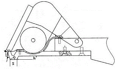
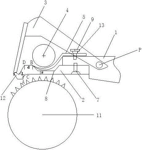
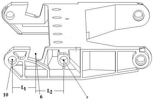
[0024] like figure 2 and image 3 As shown, a novel combing machine nipper mechanism includes a lower nipper seat 1, a lower nipper 2 is fixed in front of the lower nipper seat 1, and a trapezoidal groove 8 is provided in the middle of the top surface of the lower nipper 2, A cotton guide plate 5 is arranged in the trapezoidal groove 8 . The front portion of the cotton guide plate 5 is arc-shaped, and the tail portion is horizontal, and the tail portion is ...


PUM

PropertyMeasurementUnit
lengthaaaaaaaaaa
lengthaaaaaaaaaa
depthaaaaaaaaaa

Abstract

The invention discloses a novel combing-machine nipper mechanism which comprises a lower nipper seat. A lower nipper plate is fixed in front of the lower nipper seat, a trapezoidal groove is formed in the middle of the top surface of the lower nipper plate, a cotton guide plate is arranged in the trapezoidal groove, the cotton guide plate is arc-shaped on the front portion and horizontal at the tail, the tail portion of the cotton guide plate is fixed on the lower nipper plate, a feed roller is arranged above the cotton guide plate, and grooves for holding the feed roller are arranged at two ends of the lower nipper seat; the front end of the bottom surface of the lower nipper plate is provided with a plane, the rear of the plane is gradually raised through circular arc transition, and the lower nipper seat is connected with an upper nipper plate connector in a hinge joint manner. By the arrangement, a cotton feed channel can be flexibly adjusted according to thickness of a small roll, distance of the center of the front end of each nipper plate, the center of each groove and hinge point of each nipper plate can be reasonably arranged, and large quantitative of small rolls and long fibers 35mm above in length are assured to be processed smoothly through a combing machine; due to the arc-raised surface, collision against the lower nipper plate by cylinder needle teeth is avoided, compressive strength of the nipper lip of the lower nipper plate is guaranteed, the nipper plates and a cylinder of the combing machine are prevented from being damaged, and production cost is obviously reduced.

Description

technical field [0001] The invention relates to the technical field of special components for cotton spinning equipment, in particular to a novel comber nipper mechanism. Background technique [0002] The main function of the nipper mechanism of the combing machine is to hold the cotton clumps for combing by the cylinder needle teeth, and send the combed clumps to the separation jaws to complete the separation and joining work. The nipper is designed to meet the following requirements: [0003] 1. Ensure the smooth feeding of cotton layers with different thicknesses; the cotton feeding channel between the lower nipper and the cotton feeding roller determines the thickness of the cotton layer processed by the combing machine (small roll quantitative); the narrower the cotton feeding channel, the more suitable The smaller the quantity of small laps is, the wider the feeding channel is, and the larger the applicable small laps are; the feeding channel of the nipper mechanism o...

Claims


Application Information

Patent Timeline
Patent Type & Authority Applications(China)
IPC IPC(8): D01G19/16
CPCD01G19/16
Inventor 任家智陈宇恒贾国欣冯清国张海洋刘红艳尚龙飞
Owner ZHONGYUAN ENGINEERING COLLEGE
Why Eureka
Try Eureka