Pressure test structure for long bored cast-in-situ pile and test method

A technology for bored piles and pressure testing, which is applied in the testing of foundation structures, foundation structure engineering, construction, etc. performance, ease of implementation, and simple operation

Active Publication Date: 2016-08-24
CENT SOUTH UNIV
View PDF5 Cites 5 Cited by
  • Summary
  • Abstract
  • Description
  • Claims
  • Application Information

AI Technical Summary

Problems solved by technology

[0007] However, the theoretical analysis and numerical simulation methods cannot reflect the real working state of the pile, and the pile side soil pressure obtained is only an approximate solution, and there are situations that deviate from the actual situation. In addition, the artificial embedded soil pressure box is only suitable for short piles and convenient Pile foundation types of artificial activities, such as artificially dug holes
[0008] The length of the existing large-diameter deep and long cast-in-situ piles has exceeded 50m, and there are uncertainties in the strata they pass through. The above three methods cannot meet the requirements of obtaining accurate soil pressure on the side of the pile.

Method used


Image

  • Pressure test structure for long bored cast-in-situ pile and test method
  • Pressure test structure for long bored cast-in-situ pile and test method
  • Pressure test structure for long bored cast-in-situ pile and test method

Examples


Embodiment 1

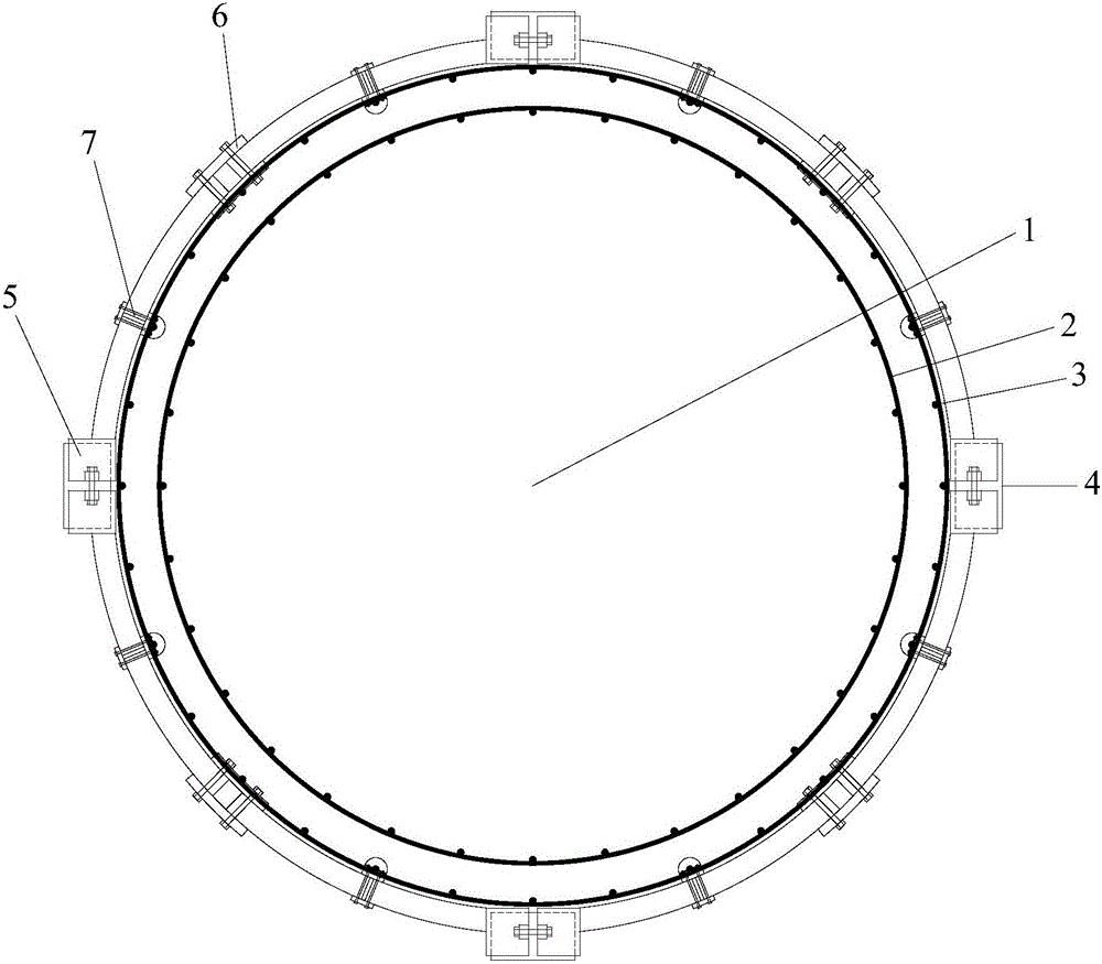
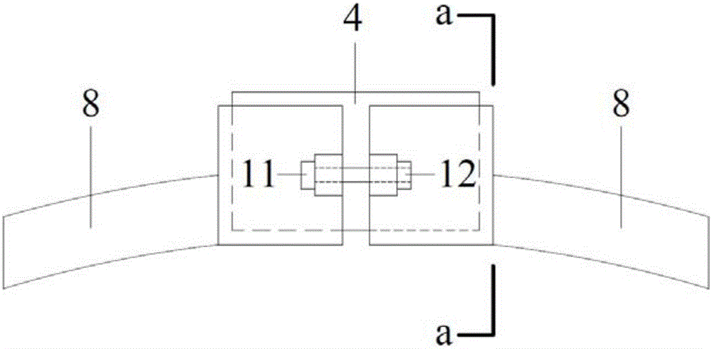
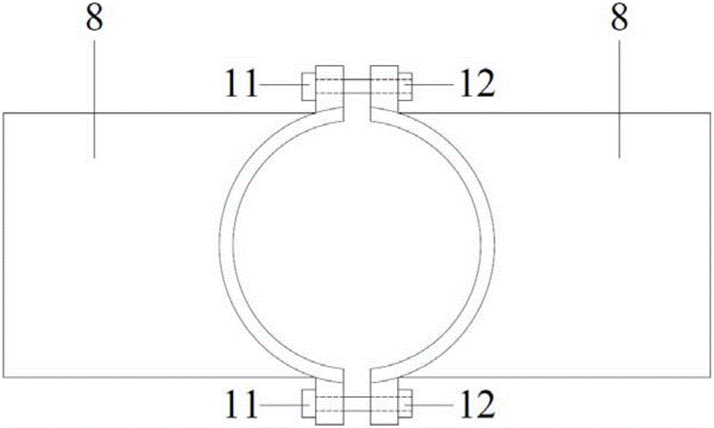
[0056] see figure 1 , figure 2 , image 3 and Figure 4 The shown large-diameter deep-length bored piles (including bored pile 1, reinforcement cage 2 and main reinforcement 3) and test method components (earth pressure box 4, earth pressure box protection and fixing device 5, earth pressure box lock The connecting part between the tightening device 6, the positioning and locking device between the connecting part and the main reinforcement of the steel cage 7, the main board 8, the auxiliary board 9, the vertical board 10, the screw 11 and the bolt 12), the pile length is 80m, and the pile side soil is respectively muddy Silty clay, silt, silt and silty clay, among them, silty silty clay up to 16m thick, silt up to 34m thick, silty sand up to 5m thick, silty clay up to 25m thick, and the pile foundation is designed as a friction pile , and bear a relatively large vertical load, the pile foundation is mechanically drilled, the ground is prefabricated with a steel cage, and...

Embodiment 2

[0058] (1) According to the "Technical Specifications for Building Pile Foundation Inspection" (JGJ 106-2003), select the appropriate earth pressure sensor according to the sensor technology and environmental characteristics, and according to the "Technical Specifications for Building Foundation Pit Engineering Monitoring" (GB 50497- 2009) Select the range of the earth pressure cell as well as the measurement accuracy and resolution;

[0059] (2) According to the "Technical Specifications for Monitoring Construction Foundation Pit Engineering" (GB 50497-2009), install the earth pressure cell into the earth pressure cell protection and fixing device. protection, and can form a good contact with the concrete on the pile side, and will not enter the earth pressure box protection and fixing device when the concrete is poured. Secondly, before locking the side of the half cylinder shell, the earth pressure box and the half cylinder The gap between the sides of the casing is filled ...


PUM


Abstract

The invention discloses a pressure test structure for a long bored cast-in-situ pile and a test method. The pressure test structure comprises a toroidal main reinforcement fixed on the cast-in-situ pile, a plurality of soil pressure box protecting and fixing devices arranged on the outer side of the main reinforcement, and a plurality of soil pressure box fixing device inter-connecting parts used for fixedly connecting every two adjacent soil pressure box protecting and fixing devices, wherein each soil pressure box fixing device inter-connecting part is locked and fixed on the outer side of the main reinforcement by a positioning and locking device; and a soil pressure box is mounted in each soil pressure box protecting and fixing device, and when the cast-in-situ pile is cast and formed in a deep and long drilling hole, the soil pressure boxes are kept in reliable contact with the outer wall surface of the cast-in-situ pile and soil around the cast-in-situ pile. The pressure test structure is easy to implement, simple to operate, favorable in effect, low in manufacturing cost and wide in application range.

Description

technical field [0001] The invention relates to a pressure test structure and a test method of deep and long bored cast-in-place piles, belonging to the field of building structure tests. Background technique [0002] Pile is a commonly used foundation type mainly used to bear the upper load and meet certain vertical displacement requirements. The bearing capacity of the pile foundation is mainly achieved through the supporting force of the pile tip and the frictional resistance of the pile side. When the formation lithology is not ideal, such as deep and thick soft soil formation, it is difficult to obtain reliable pile end bearing force, so the diameter and length of the pile are increased in exchange for greater pile side friction. The two key factors affecting the magnitude and performance of the pile side frictional resistance are the pile side soil pressure and the friction performance between the pile and soil. The latter can be easily obtained by indoor experiments....

Claims


Application Information

Patent Timeline
Patent Type & Authority Applications(China)
IPC IPC(8): E02D33/00
CPCE02D33/00
Inventor 邓东平李亮赵炼恒
Owner CENT SOUTH UNIV
Why Eureka
Try Eureka