Concrete-column cast-in-place structure movable-formwork supporting system and construction method

A technology of formwork support and concrete columns, which is applied to the joints of formwork/formwork/work frame, building structure, and on-site preparation of building components. It can solve the problems of long time occupation of mechanical equipment, slow construction progress, and labor costs. Problems such as high cost, achieving significant technical and economic benefits, reducing construction costs, and low labor intensity

Active Publication Date: 2016-08-24
上海电力建筑工程有限公司 +1
View PDF5 Cites 1 Cited by
  • Summary
  • Abstract
  • Description
  • Claims
  • Application Information

AI Technical Summary

Problems solved by technology

This construction process has the following defects: in the early stage of construction, it is necessary to set up a full house of scaffolding to fix, position, and support the formwork, and the amount of turnover materials such as fasteners and scaffolding is large, which increases the cost; and the positioning workload is large, adjustment is inconvenient, and the construction progress is slow. , the mechanical equipment takes a long time and increases the cost; the construction of the full hall scaffolding mainly depends on labor, and the labor cost is high

Method used


Image

  • Concrete-column cast-in-place structure movable-formwork supporting system and construction method
  • Concrete-column cast-in-place structure movable-formwork supporting system and construction method
  • Concrete-column cast-in-place structure movable-formwork supporting system and construction method

Examples


Embodiment Construction

[0035] The present invention will be further described below in combination with specific embodiments.

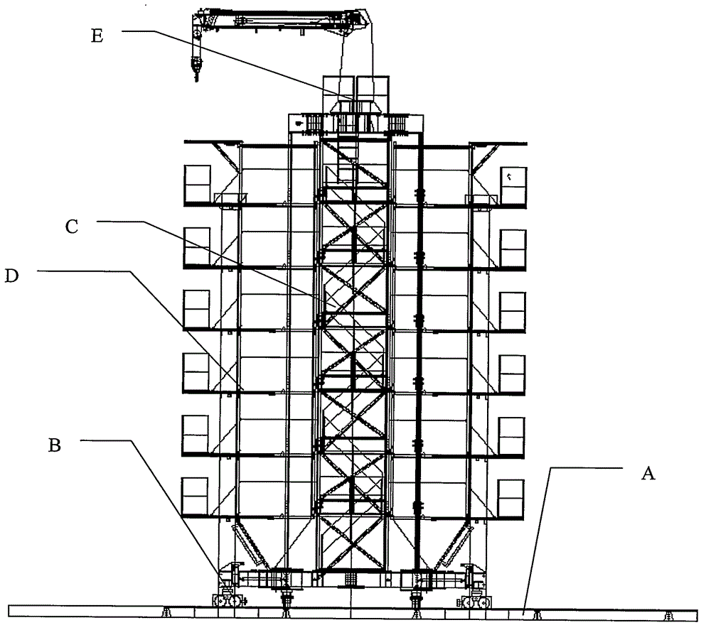
[0036] The mobile formwork support system of the concrete column cast-in-place structure of the present invention, such as figure 1 As shown, it includes track system (A), underframe system (B), frame structure system (C), turning platform formwork support system (D), top girder and crane system (E), which are sequentially installed before use. Assembled to form a whole.

[0037] The specific construction method is as follows:

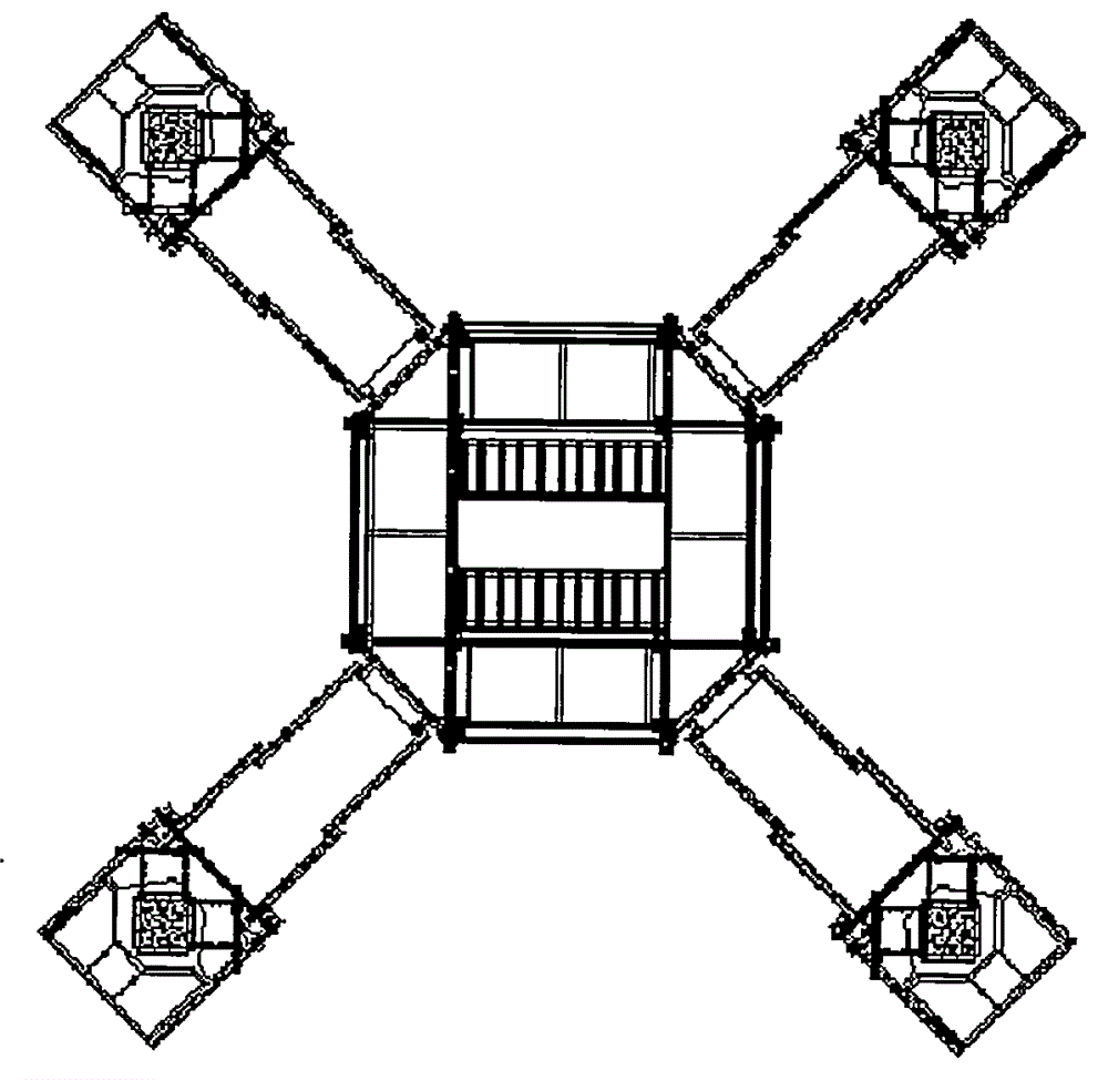
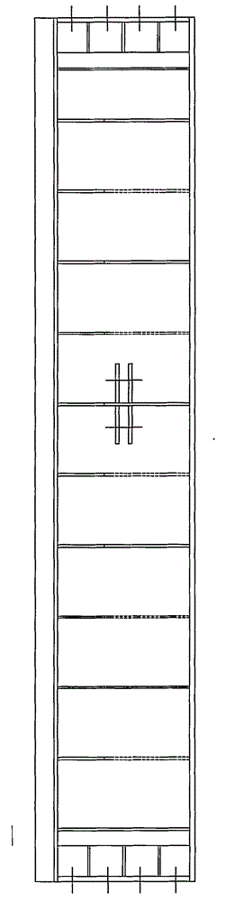
[0038] The first step is to make the track system ( image 3 , 4 ) are connected into a whole through bolts (1), and the whole is hoisted in place.

[0039] In the second step, after the welded inner beam (4) of the underframe is connected through the bolt (4) there, the inner web bar (7) and the outer inclined bar (3, 6) are connected through the pin shaft and the bolt Connect with the inner beam (4), and then connect the X direction wheel (9)...


PUM


Abstract

The invention discloses a concrete-column cast-in-place structure movable-formwork supporting system and a construction method. The concrete-column cast-in-place structure movable-formwork supporting system is characterized in that the whole system is mainly composed of a frame structure system and a supporting platform formwork supporting system, and the parts are of all-steel structures; a bottom frame system comprises eight wheels, and the eight wheels are divided into two sets; in other words, four wheels are in the X direction, the other four wheels are in the Y direction, and outer support legs of the bottom frame system are connected with table frames through pins to form a whole; four supporting platforms are arranged on each layer in the supporting platform formwork supporting system, and all the platforms are fixedly connected with frame system stand columns through pins. By means of the concrete-column cast-in-place structure movable-formwork supporting system, site erecting of full hall scaffolds can be avoided, the system is a supporting system integrating walking, hoisting, formworks, supporting and construction platforms, four columns can be poured in the one-time formwork positioning and erecting process, and the hoisting function, the X-direction walking function, the Y-direction walking function and the like can be achieved through the system. Due to platform adjustable-section length variation, formwork short-support length variation and track length variation, cast-in-place construction of water trickling component columns with all kinds of column spaces and column sections can be achieved so that the requirements of different project-design parameters can be met.

Description

technical field [0001] This invention is a mobile formwork support system and construction method developed for concrete columns or concrete columns of other buildings for on-site pouring construction. It is mainly used for the in-situ construction of concrete columns, and is especially suitable for on-site pouring of columns with standard column spacing. The technology can be conveniently and quickly positioned in place, the formwork can be erected, and four column heads can be poured after one positioning, which can be used repeatedly without setting up a whole house of scaffolding. The upper part of the system is equipped with a crane and the lower part is equipped with a walking mechanism, which can realize the hoisting of steel bars and formwork and the displacement of the track, and then realize the walking function of the system, which can be reused for pouring of column heads. Background technique [0002] At present, the traditional construction technology is to set...

Claims


Application Information

Patent Timeline
Patent Type & Authority Applications(China)
IPC IPC(8): E04G17/00E04G21/00
Inventor 王立伟郑谦文柏斯海李伟莫荣奂孙小婷
Owner 上海电力建筑工程有限公司
Why Eureka
Try Eureka