Well completion pipe string

A completion pipe string and casing technology, applied in drill pipe, casing, drilling equipment and other directions, can solve the problems of casing string buckling, delay in construction progress, large casing string, etc., to avoid radial deviation, Reduce the effect of mutual wear

Inactive Publication Date: 2016-08-24
CHENGDU NORTH OIL EXPLORATION DEV TECH
View PDF6 Cites 9 Cited by
  • Summary
  • Abstract
  • Description
  • Claims
  • Application Information

AI Technical Summary

Problems solved by technology

[0002] The completion of extended-reach horizontal wells is characterized by high inclination, long open hole, and long section of stabilizing well. In the case of high inclination angle, the casing string is close to the lower well wall. After entering the horizontal section, the casing string will be completely attached On the lower well wall, the contact section between the casing string and the formation is very long at this time, and the casing string is loaded on the horizontal section of the well wall. The friction resistance of the formation to the casing string is quite large, and it cannot even go down to the bottom of the well by its own weight. , it needs to be pressurized to slide down, and it is easy to cause the casing string to buckle, and it may even cause the casing string to be stuck in the curved section of the wellbore due to the high rigidity of the casing and cannot be run in
Due to the high frictional resistance of the casing string, the casing string often cannot go down to the predetermined position smoothly, delaying the construction progress, affecting the subsequent oil recovery effect, and even causing serious consequences of wellbore scrapping

Method used


Image

  • Well completion pipe string
  • Well completion pipe string

Examples


Embodiment 1

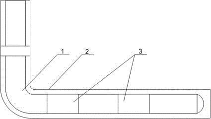
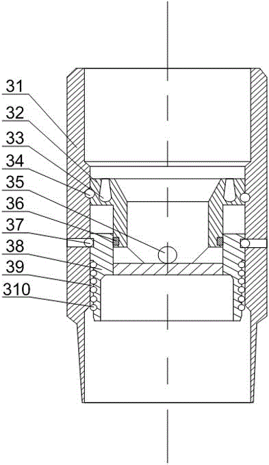
[0023] Such as figure 1 with figure 2 As shown, this embodiment includes a casing 1 placed in the wellbore 2, and two floating collars 3 are arranged on the horizontal section of the casing 1, and the floating collars 3 include a casing 31, an upper sliding Sleeve 32 and sliding sleeve 38, the upper sliding sleeve 32 is composed of interconnecting parts and a shearing part with the same outer diameter as the inner diameter of the housing 31, the shearing part is supported on the upper section of the inner wall of the housing 31 by the upper shear nail 34, and slides down The sleeve 38 is supported on the lower section of the inner wall of the housing 31 by the lower shear nail 37. The communication part is placed in the lower sleeve 38, and a discharge hole 35 is opened on the communication part. When the upper shear nail 34 is not cut off, The lower sleeve 38 seals the discharge hole 35, and when the upper shear nail 34 is cut off, the upper sliding sleeve 32 moves along th...


PUM


Abstract

The invention discloses a well completion pipe string comprising a bushing. Two floating couplings are arranged on a horizontal section of the bushing. Each floating coupling comprises a shell, an upper slide sleeve and a lower slide sleeve, the upper slide sleeve comprises a communication portion and a shear portion, the shear portion is supported on the upper section of the inner wall of the shell through an upper shear pin, the lower slide sleeve is supported on the lower section of the inner wall of the shell through a lower shear pin, the communication portion is disposed in the lower slide sleeve, and a discharge hole is formed in the communication portion; an annular steady flow groove is formed in the upper end face of the shear portion, and the width of the steady flow groove decreases axially along the shear portion. The floating couplings are arranged on the bushing to enable the bushing to be filled with air; since the bushing below the floating couplings is filled with air, after the section of the bushing enters a horizontal well section, gravity acting on the horizontal well wall is reduced, friction force between the bushing and the well wall is reduced accordingly, thrust pushing the bushing forward is reduced, and accordingly quality of well cementation of the horizontal section is improved beneficially, and convenience is brought to the bushing to lower to the design position.

Description

technical field [0001] The invention relates to the field of oil exploitation, in particular to a completion pipe string. Background technique [0002] The completion of extended-reach horizontal wells is characterized by high inclination, long open hole, and long section of stabilizing well. In the case of high inclination angle, the casing string is close to the lower well wall. After entering the horizontal section, the casing string will be completely attached On the lower well wall, the contact section between the casing string and the formation is very long at this time, and the casing string is loaded on the horizontal section of the well wall. The friction resistance of the formation to the casing string is quite large, and it cannot even go down to the bottom of the well by its own weight. , It needs to be pressurized to slide down, and it is easy to cause the casing string to buckle, and it may even cause the casing string to be stuck in the curved section of the w...

Claims


Application Information

Patent Timeline
Patent Type & Authority Applications(China)
IPC IPC(8): E21B17/08E21B17/10E21B7/20E21B33/13
CPCE21B17/08E21B7/20E21B17/1085E21B33/13
Inventor 何巍徐兵邓勇柳世成张艺久欧阳静芸
Owner CHENGDU NORTH OIL EXPLORATION DEV TECH
Why Eureka
Try Eureka