High-precision combined cutter handle

A high-precision, tool handle technology, applied in the direction of tool holders, etc., can solve the problems of radial runout between nut and tool handle and jacket, radial deviation between nut and tool handle, and affecting tool assembly accuracy, etc., to increase the length , Avoid radial deviation, facilitate assembly and disassembly

Active Publication Date: 2022-02-01
袁龙
View PDF7 Cites 0 Cited by
  • Summary
  • Abstract
  • Description
  • Claims
  • Application Information

AI Technical Summary

Problems solved by technology

[0002] With the development of industry in the market, the demand for ultra-high-precision related equipment, such as tool holders for machine tools, is increasing. At the same time, the processing precision of machine tool equipment is also getting higher and higher. Machine tools are the mother of industrial processing. The precision, stability and rigidity of the used HSK / BT / ISO series tool holders play a decisive role. The existing tool holders and tools usually use nuts and jackets to fix the tools on the tool holders. The handle is threadedly connected. However, when the nut is fastened to the handle and the tool, there is always a certain error in the assembly. When the nut, the handle and the jacket are tightened, radial runout will occur, resulting in a gap between the nut and the handle. The radial deviation between them affects the assembly accuracy of the tool

Method used


Image

  • High-precision combined cutter handle
  • High-precision combined cutter handle
  • High-precision combined cutter handle

Examples


Embodiment 1

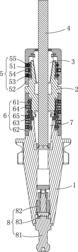
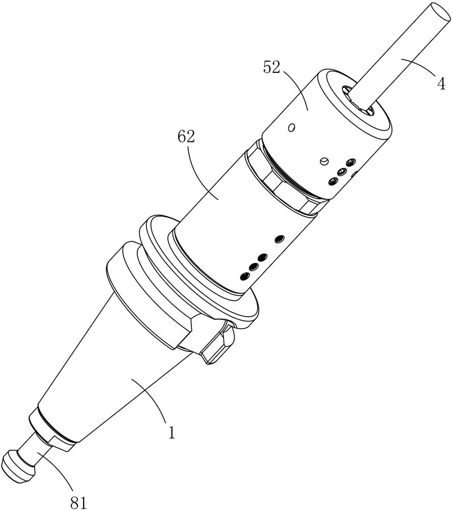
[0034] Please refer to Figure 1 to Figure 4 , a high-precision combined handle, including a main handle 1 and an extended handle 2, the front end of the extended handle 2 is connected with an elastic collet 3, the elastic collet 3 is used to hold the tool 4, and the elastic collet 3 passes through the first lock The tightening assembly 5 is fixedly connected with the extension handle 2, and the rear end of the extension handle 2 is fixedly connected with the front end of the main handle 1 through the second locking assembly 6; The first locking ring 51 threadedly connected to the handle 2, the nut 52 sleeved on the outer periphery of the first locking ring 51 and connected to the elastic collet 3, and the first locking ring 51 and the nut 52 are stuck between the first locking ring 51 and the nut 52 The side of the nut 52 is provided with a first fixing member 54 for limiting the first locking ring 51 and a second fixing member 55 for limiting the first ball set 53 . Wherein...

Embodiment 2

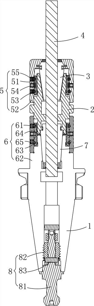
[0044] Please refer to Figure 5 to Figure 8 , the difference from Example 1 is that the rear end of the main handle 1 in this embodiment is not provided with a pull stud assembly 8, and the rear end of the main handle 1 forms a mounting hole that matches the machine tool, so that the main handle 1 can be easily installed on the machine tool. superior. The second elastic collet 7 located on the main handle 1 is used to clamp the central water outlet connecting pin 9, the upper and lower ends of the central water outlet connecting pin 9 are provided with sealing gaskets 10, and the bottom end of the central water outlet connecting pin 9 is still A sealing fixing nut 11 is provided. The structure of the main handle 1 of this embodiment is different from that of Embodiment 1, and can be selected according to different actual needs during actual use. Please refer to Figure 5 and Figure 7 , the second locking ring 61 of this embodiment can also be one or more than two; On th...

Embodiment 3

[0046] Please refer to Figure 9 and Figure 10 , The difference from Embodiment 1 and Embodiment 2 is that this embodiment does not set the extended handle 2, that is, the tool 4 can be directly fixed on the main handle 1 through the elastic collet 3 and the first locking member 5. Please refer to Figure 11 and Figure 12 , this embodiment provides another embodiment, in this embodiment, the position where the tool 4 was originally installed on the main handle 1 is changed to install a knife bar 12, and a blade 13 is installed on the knife bar 12, wherein the knife bar 12 passes through The knife rod fastening nut 14 is fixed on the main handle 1 , the knife rod fastening nut 14 is sleeved on the outer periphery of the knife rod 12 , and the bottom of the knife rod 12 is also provided with a knife rod fixing nut 15 . This structure is also for avoiding radial runout when the tool holder 12 is installed on the main handle 1, so as to improve its installation accuracy.

[...


PUM


Abstract

The invention relates to a high-precision combined cutter handle, which comprises a main handle and a lengthened handle, wherein the front end of the lengthened handle is connected with an elastic collet, the elastic collet is used for clamping a cutter, the elastic collet is fixedly connected with the lengthened handle through a first locking assembly, and the rear end of the lengthened handle is fixedly connected with the front end of the main handle through a second locking assembly; the first locking assembly comprises a first locking ring arranged on the periphery of the lengthened handle in a sleeving mode and connected with the lengthened handle in a threaded mode, a nut arranged on the periphery of the first locking ring in a sleeving mode and connected with the elastic collet, and a first ball set clamped between the first locking ring and the nut. A first fixing piece used for limiting the first locking ring and a second fixing piece used for limiting the first ball set are arranged on the side face of the nut. The first locking piece is of a split structure, radial deviation between the nut and the cutter handle can be effectively avoided, and therefore the ultra-high-precision assembling requirement is met.

Description

technical field [0001] The invention relates to the technical field of machine tool processing, in particular to a high-precision combined tool holder. Background technique [0002] With the development of industry in the market, the demand for ultra-high-precision related equipment, such as tool holders for machine tools, is increasing. At the same time, the processing precision of machine tool equipment is also getting higher and higher. Machine tools are the mother of industrial processing. The precision, stability and rigidity of the used HSK / BT / ISO series tool holders play a decisive role. The existing tool holders and tools usually use nuts and jackets to fix the tools on the tool holders. The handle is threadedly connected. However, when the nut is fastened to the handle and the tool, there is always a certain error in the assembly. When the nut, the handle and the jacket are tightened, radial runout will occur, resulting in a gap between the nut and the handle. The ...

Claims


Application Information

Patent Timeline
IPC IPC(8): B23B29/04
CPCB23B29/04
Inventor 袁龙
Owner 袁龙
Why Eureka
Try Eureka