Flow string

A production pipe and casing technology, applied in the field of production pipe strings, can solve problems such as delay in construction progress, buckling of casing strings, and high frictional resistance of casing strings, and achieve the effects of reducing mutual wear and avoiding radial deviation

Inactive Publication Date: 2018-03-09
邹跃明
View PDF0 Cites 0 Cited by
  • Summary
  • Abstract
  • Description
  • Claims
  • Application Information

AI Technical Summary

Problems solved by technology

[0002] The completion of extended-reach horizontal wells is characterized by high inclination, long open hole, and long section of stabilizing well. In the case of high inclination angle, the casing string is close to the lower well wall. After entering the horizontal section, the casing string will be completely attached On the lower well wall, the contact section between the casing string and the formation is very long at this time, and the casing string is loaded on the horizontal section of the well wall. The friction resistance of the formation to the casing string is quite large, and it cannot even go down to the bottom of the well by its own weight. , it needs to be pressurized to slide down, and it is easy to cause the casing string to buckle, and it may even cause the casing string to be stuck in the curved section of the wellbore due to the high rigidity of the casing and cannot be run in
Due to the high frictional resistance of the casing string, the casing string often cannot go down to the predetermined position smoothly, delaying the construction progress, affecting the subsequent oil recovery effect, and even causing serious consequences of wellbore scrapping

Method used


Image

  • Flow string
  • Flow string

Examples


Embodiment 1

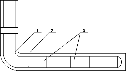
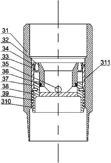
[0023] Such as figure 1 and figure 2 As shown, this embodiment includes a casing 1 placed in the wellbore 2, and two floating collars 3 are arranged on the horizontal section of the casing 1, and the floating collars 3 include a casing 31, a fixed sleeve The sleeve 311, the upper sliding sleeve 32 and the lower sleeve 38, the fixed sleeve 311 is fixed on the upper part of the inner wall of the housing 31 through the upper shear nail 34, and the upper sliding sleeve 32 is composed of interconnecting parts connected with each other and the outer diameter is the same as the inner diameter of the housing 1. The shearing part is formed on the inner wall of the upper part of the fixed sleeve 311, the sliding sleeve 38 is supported on the lower part of the inner wall of the fixing sleeve 311 by the lower shear nail 37, and the lower sleeve 38 is supported on the housing 31 by the lower shear nail 37. In the lower part of the inner wall, the communicating portion is placed in the sl...


PUM


Abstract

The invention discloses a flow string, which comprises a casing. Two floating couplings are arranged on the horizontal segment of the casing, the floating coupling comprises a shell body, a fixing sleeve, an upper sliding bushing and a lower sliding bushing. The upper sliding bushing comprises a communication portion and a cutting portion, the cutting portion is supported on the upper segment of the inner wall of the fixing sleeve through an upper cutting nail, the lower sliding bushing is supported on the lower segment of the inner wall of the fixing sleeve through a lower cutting nail, the communication portion is disposed in the lower sliding bushing, and a flow discharging hole is formed in the communication portion; a flow stabilizing groove is formed in the upper end face of the cutting portion, and the width of the groove successively decreases upward in the axial direction of the cutting portion. By installing a plurality of floating couplings on the casing, the casing is filled with air. Because the casing under the floating couplings is full of air, after the casing enters the horizontal well segment, the gravity force acted on the horizontal well wall is reduced, accordingly the friction between the casing and the well wall is decreased, the pushing force of pushing the casing to move forward is reduced, and therefore the improvement of well cementing quality of thehorizontal segment is facilitated, and the casing moving downward to the designed position is facilitated.

Description

technical field [0001] The invention relates to the field of petroleum exploitation, in particular to an oil production string. Background technique [0002] The completion of extended-reach horizontal wells is characterized by high inclination, long open hole, and long section of stabilizing well. In the case of high inclination angle, the casing string is close to the lower well wall. After entering the horizontal section, the casing string will be completely attached On the lower well wall, the contact section between the casing string and the formation is very long at this time, and the casing string is loaded on the horizontal section of the well wall. The friction resistance of the formation to the casing string is quite large, and it cannot even go down to the bottom of the well by its own weight. , It needs to be pressurized to slide down, and it is easy to cause the casing string to buckle, and it may even cause the casing string to be stuck in the curved section of...

Claims


Application Information

Patent Timeline
Patent Type & Authority Applications(China)
IPC IPC(8): E21B17/08E21B34/08
CPCE21B17/08E21B34/08E21B2200/06
Inventor 邹跃明
Owner 邹跃明
Why Eureka
Try Eureka