Rotating compressor low in exhaust oil content

A rotary compressor and oil content technology, applied in the field of rotary compressors, can solve the problem of high oil content in the exhaust, and achieve the effects of reduced oil content in the exhaust, stable oil volume, and good speed change characteristics

Active Publication Date: 2016-08-24
GUANGXI UNIV
View PDF8 Cites 10 Cited by
  • Summary
  • Abstract
  • Description
  • Claims
  • Application Information

AI Technical Summary

Problems solved by technology

Because the exhaust gas of the traditional rotary compressor has not been separated from oil and gas and returned to the lubricating oil, the oil content in the exhaust gas is relatively large

Method used


Image

  • Rotating compressor low in exhaust oil content
  • Rotating compressor low in exhaust oil content
  • Rotating compressor low in exhaust oil content

Examples


Embodiment 1

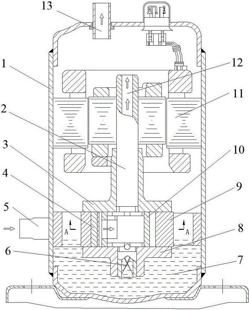
[0027] figure 1 The rotary compressor with low exhaust oil content shown includes a housing 1 , a crankshaft 2 , an upper end cover 3 , a guide rail 4 , a lower end cover 8 , a cylinder 9 , a swing rotor 10 and a motor 11 . An air intake pipe 5 and an exhaust pipe 13 are welded on the housing 1 . There is an axial oil passage below the crankshaft 2, and an oil-absorbing sheet 6 is housed in the axial oil passage. There is an oil pool 7 at the bottom of the housing 1, and the oil-absorbing sheet 6 and the axial oil channel are always under the liquid level of the oil pool 7. The compressor is driven by a motor 11, and the rotor of the motor is coaxial with the compressor. During the working process of the compressor, the air is sucked from the suction pipe 5, and enters the working chamber composed of the upper end cover 3, the guide rail 4, the lower end cover 8, the cylinder 9 and the swing rotor 10 through the air intake hole on the cylinder 9. After compression, , discha...

Embodiment 2

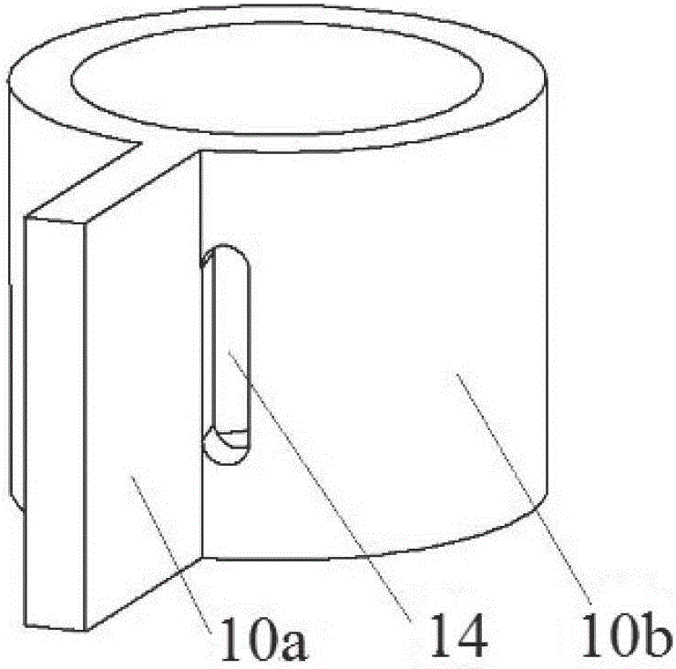
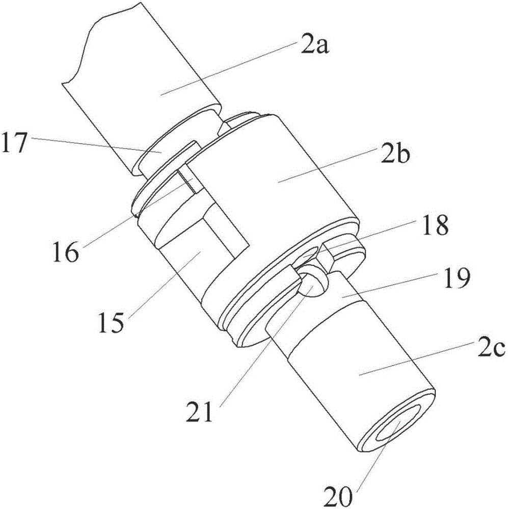
[0037] A rotary compressor with low exhaust oil content includes a casing 1 , a crankshaft 2 , an upper end cover 3 , a guide rail 4 , a lower end cover 8 , a cylinder 9 , a swing rotor 10 and a motor 11 . The crankshaft 2 includes a main shaft 2a, an eccentric wheel 2b and a secondary shaft 2c, and the swing rotor 10 is sleeved on the eccentric wheel 2b. Air intake hole 24 is arranged on the cylinder 9, and exhaust hole 14 is arranged on the swing rotor 10. An axial air channel 12 is opened in the center of the main shaft 2a, and an axial oil channel 20 is opened in the center of the auxiliary shaft 2c. An exhaust cavity 15 and an oil return groove 16 are opened on the eccentric wheel 2b. The exhaust chamber 15 communicates with the axial air passage 12 . One end of the oil return groove 16 communicates with the exhaust chamber 15 , and the other end communicates with the upper oil chamber 25 jointly formed by the upper end cover 3 , the swing rotor 10 and the crankshaft 2 ...


PUM


Abstract

A rotating compressor low in exhaust oil content comprises a shell, a crankshaft, an upper end cover, a guide rail, a lower end cover, a cylinder, a swing rotor and a motor. The crankshaft comprises a main shaft, an eccentric wheel and an auxiliary shaft. The eccentric wheel is sleeved with the swing rotor. A gas inlet hole is formed in the cylinder. The swing rotor is provided with an exhaust hole. An axial gas way is formed in the center of the main shaft. An axial oil way is formed in the center of the auxiliary shaft. An exhaust cavity and an oil return groove are formed in the eccentric wheel. The exhaust cavity communicates with the axial gas way. One end of the oil return groove communicates with the exhaust cavity. The other end of the oil return groove communicates with an upper oil cavity jointly formed by the upper end cover, the swing rotor and the crankshaft. According to the compressor, compressed gas enters the exhaust cavity through the exhaust hole, and oil and gas separation is performed under the effect of the centrifugal force. Separated lubricating oil returns to an oil pond in the shell, and separated gas enters the shell through the axial gas way and then is discharged. The compressor is high in system energy efficiency and good in reliability and speed changing characteristic.

Description

technical field [0001] The invention relates to the technical field of rotary compressors, in particular to a rotary compressor with low exhaust oil content. Background technique [0002] Rotary compressors are widely used due to their advantages of small size, light weight and simple structure. For example, rotary compressors are widely used in room air conditioners. Since there is contact and relative movement between the parts in the rotary compressor, and the working chamber is sealed with gaps, lubricating oil is usually required in the compressor cylinder to achieve the effect of lubrication and sealing. When the compressor is exhausted, the lubricating oil is discharged together with the gas, which reduces the lubricating oil in the oil pool of the compressor, thus affecting the reliability of the compressor. Excessive lubricating oil enters the pipeline system behind the compressor along with the gas, which will also cause problems that cannot be ignored. For examp...

Claims


Application Information

Patent Timeline
Patent Type & Authority Applications(China)
IPC IPC(8): F04C21/00F04C29/02F04C29/12F04C29/00
CPCF04C21/002F04C29/00F04C29/02F04C29/023F04C29/026F04C29/12F04C2240/20F04C2240/601F04C2240/603
Inventor 潘树林潘曦王满
Owner GUANGXI UNIV
Why Eureka
Try Eureka