Discharge valve assembly of compressor and compressor having same
A technology for exhaust valves and compressors, which is applied in the field of compressors, and can solve problems such as the length of the bearing valve seat, the unfavorable optimization of compressor performance and cost, and the impact on the strength of the bottom surface of the bearing, so as to achieve small deformation, benefit performance and cost, and performance and cost-optimized effects
- Summary
- Abstract
- Description
- Claims
- Application Information
AI Technical Summary
Problems solved by technology
Method used
Image
Examples
Embodiment 1
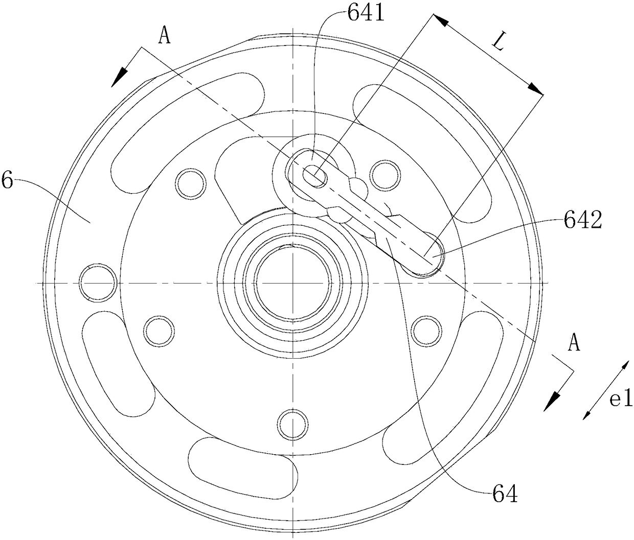
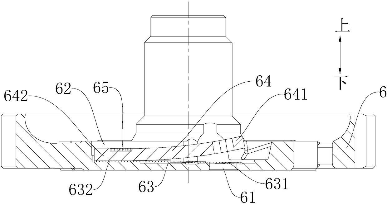
[0051] refer to Figure 2-Figure 4 , in this embodiment, the valve plate 63 is formed in a substantially elongated shape. Compared with the traditional valve plate 63, the length L of the elongated valve plate 63 can be set to be smaller. The shape of the lift limiter 64 is substantially the same as that of the valve plate 63 , and the shape of the valve plate groove 62 matches the shape of the valve plate 63 .
[0052] The tail portion 642 of the lift limiter 64 is connected by laser welding to the side wall of the valve plate groove 62, and the weld 65 between the lift limiter 64 and the valve plate groove 62 is located on the upper edge of the lift limiter 64 The contact position with the disc groove 62. Thus, the welding process operation is facilitated, thereby facilitating the welding connection between the lift limiter 64 and the side wall of the valve plate groove 62 .
[0053] Further, the weld 65 between the lift limiter 64 and the valve plate groove 62 includes at...
Embodiment 2
[0057] The difference between the exhaust valve assembly of this embodiment and the above-mentioned first embodiment lies in the shapes of the valve plate groove 62, the valve plate 63 and the lift limiter 64, and the relationship between the lift limiter 64 and the valve plate groove 62. 65 positions between the welds. Other structures of the exhaust valve assembly of this embodiment are generally the same as those of the above embodiment, and will not be repeated here.
[0058] refer to Figure 5-Figure 8 , in this embodiment, the weld 65 between the lift limiter 64 and the valve slot 62 is located at the contact position between the tail end edge of the lift limiter 64 and the valve slot 62 . The tail portion 642 of the lift limiter 64 is in the first direction (see Figure 5 with Figure 8 The size in the e2 direction) is smaller than that in the second direction (refer to Figure 5 with Figure 8 In the e3 direction), the first direction is parallel to the line direc...
PUM
 Abstract
Description
Claims
Application Information
 - R&D
- Intellectual Property
- Life Sciences
- Materials
- Tech Scout
- Unparalleled Data Quality
- Higher Quality Content
- 60% Fewer Hallucinations
Browse by: Latest US Patents, China's latest patents, Technical Efficacy Thesaurus, Application Domain, Technology Topic, Popular Technical Reports.
© 2025 PatSnap. All rights reserved.Legal|Privacy policy|Modern Slavery Act Transparency Statement|Sitemap|About US| Contact US: help@patsnap.com


