
Efficient heat insulation guide pipe bracket

A oriented and efficient technology, which is applied in the direction of protecting pipelines, pipeline supports, and pipeline protection through heat insulation, can solve the problems of reduced allowable load capacity, reduced bearing capacity, and easy damage to the heat insulation layer, so as to enhance integration and improve The effect of bearing capacity and good wear resistance

Inactive Publication Date: 2016-08-24
JIANGSU BAOHENG PIPE FITTINGS CO LTD
View PDF0 Cites 10 Cited by
  • Summary
  • Abstract
  • Description
  • Claims
  • Application Information

AI Technical Summary

Problems solved by technology

[0002] All fields of production and life use high-temperature thermal energy. High-temperature thermal energy needs to be transported through heating network pipes. The heating network pipes are usually laid in the air, so heat-insulating pipe supports with supporting functions are required. A heat insulation layer is set between the hoops to reduce the heat loss during pipeline transmission, but the fusion performance between the hoops and the heat insulation layer of the heat insulation pipe support in the prior art is poor, and it is easy to crack. During transportation and installation, the heat insulation The layer is easily damaged, resulting in a decrease in bearing capacity and large energy loss. Therefore, during use, the allowable load capacity decreases and the heat insulation effect is poor, which cannot meet the needs of the project.

Method used


Image

  • Efficient heat insulation guide pipe bracket
  • Efficient heat insulation guide pipe bracket
  • Efficient heat insulation guide pipe bracket

Examples


Embodiment Construction

[0021] The present invention will be further described below according to the accompanying drawings and in conjunction with the embodiments.

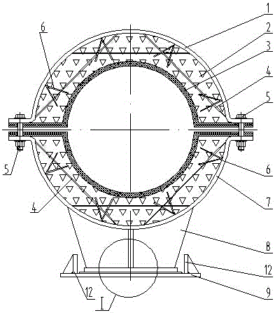
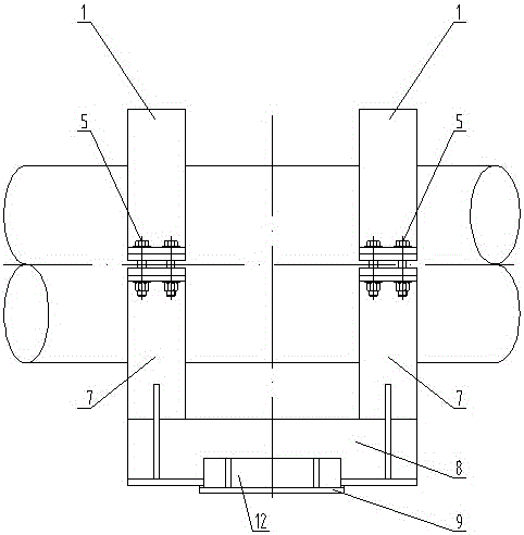
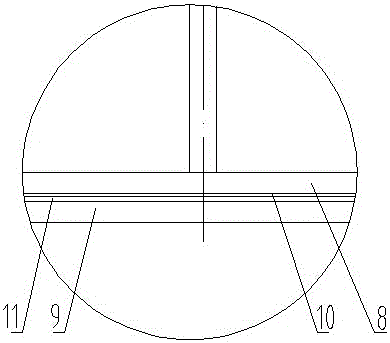
[0022] The high-efficiency heat-insulating guide pipe support shown in the attached figure includes upper hoop 1, heat-insulation tile 2, high-temperature-resistant soft thermal insulation material 3, pull rod 4, bolt fastener 5, anchor nail 6, lower hoop 7, The base 8, the base 9, the upper sliding plate 10, the lower sliding plate 11, and the guide supports 12 on the left and right sides of the base 9; the upper hoop 1 and the lower hoop 7 are all semi-ring structures, and the two sides extend to form At the fixed end, the inner walls of the upper hoop 1 and the lower hoop 7 are poured with heat-insulating tiles 2, and the inner walls of the heat-insulating tiles 2 are pasted with high-temperature-resistant soft thermal insulation materials; the upper hoop 1 and the lower hoop 7 are fixed by The bolt fasteners 5 at the ends are connec...


PUM


Abstract

The invention discloses an efficient heat insulation guide pipe bracket which comprises an upper hoop, heat insulation tile blocks, high-temperature-resistant soft heat preservation materials, bolt fasteners, a lower hoop, a base and a foundation bed. The upper hoop and the lower hoop are each of a semi-ring structure, and the two sides of the upper hoop and the two sides of the lower hoop extend to form fixing ends. The heat insulation tile blocks are poured on both the inner wall of the upper hoop and the inner wall of the lower hoop. The high-temperature-resistant soft heat preservation materials adhere to the inner walls of the heat insulation tile blocks. The upper hoop and the lower hoop are connected through the bolt fasteners arranged at the fixing ends. The lower hoop is connected to the base in a welded mode. The bottom of the base is provided with an upper sliding plate which is arranged on a lower sliding plate above the foundation bed. Accordingly, the efficient heat insulation guide pipe bracket is formed. Anchor nails and pull rods are additionally arranged between the upper hoop and the heat insulation tile blocks and additionally arranged between the lower hoop and the heat insulation tile blocks. According to the efficient heat insulation guide pipe bracket, by the adoption of the structural form that the anchor nails and the pull rods are additionally arranged between the upper hoop and the heat insulation tile blocks and additionally arranged between the lower hoop and the heat insulation tile blocks, the load bearing capacity of the pipe bracket is ensured, the loading capacity is high, and the heat transfer insulating effect is good.

Description

technical field [0001] The invention relates to a pipe fixing and supporting device, in particular to a heat-insulating pipe holder. Background technique [0002] All fields of production and life use high-temperature thermal energy. High-temperature thermal energy needs to be transported through heating network pipes. The heating network pipes are usually laid in the air, so heat-insulating pipe supports with supporting functions are required. A heat insulation layer is set between the hoops to reduce the heat loss during pipeline transmission, but the fusion performance between the hoops and the heat insulation layer of the heat insulation pipe support in the prior art is poor, and it is easy to crack. During transportation and installation, the heat insulation The layer is easily damaged, resulting in a decrease in bearing capacity and large energy loss. Therefore, during use, the allowable load capacity decreases and the heat insulation effect is poor, which cannot meet ...

Claims


Application Information

Patent Timeline
Patent Type & Authority Applications(China)
IPC IPC(8): F16L3/10F16L59/02
CPCF16L3/10F16L59/02
Inventor 王鹏
Owner JIANGSU BAOHENG PIPE FITTINGS CO LTD
Learn More