A steam cycle system

A technology of circulation system and steam, applied in the field of steam circulation system, can solve problems such as low utilization rate of steam energy

Active Publication Date: 2018-09-14
ZHUZHOU STEAM ENERGY SAVING TECH CO LTD
View PDF6 Cites 1 Cited by
  • Summary
  • Abstract
  • Description
  • Claims
  • Application Information

AI Technical Summary

Problems solved by technology

[0005] In view of this, the object of the present invention is to provide a steam cycle system, which can effectively solve the problem of relatively low utilization rate of steam energy

Method used


Image

  • A steam cycle system

Examples


Embodiment Construction

[0022] The embodiment of the invention discloses a steam cycle system to effectively solve the problem of relatively low utilization rate of steam energy.

[0023] The following will clearly and completely describe the technical solutions in the embodiments of the present invention with reference to the accompanying drawings in the embodiments of the present invention. Obviously, the described embodiments are only some, not all, embodiments of the present invention. Based on the embodiments of the present invention, all other embodiments obtained by persons of ordinary skill in the art without making creative efforts belong to the protection scope of the present invention.

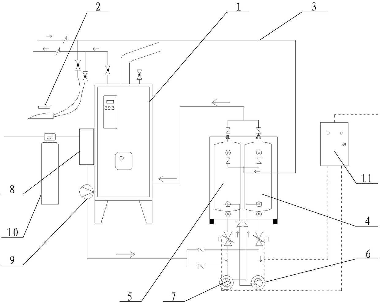
[0024] see figure 1 , figure 1 A schematic structural diagram of a steam cycle system provided by an embodiment of the present invention.

[0025] In a specific embodiment, this embodiment provides a steam cycle system, including a boiler 1, steam equipment 2, a steam return pipe 3 and a pumping device, ...


PUM


Abstract

The invention discloses a steam circulation system, comprising a boiler and steam utilization equipment communicated with the steam outlet of the boiler. The steam circulation system also comprises a return tube of which one end is communicated with the steam outlet of the steam utilization equipment, and a pumping device communicated with the other end of the return tube. The outlet of the pumping device is communicated with the inlet of the boiler. High-temperature steam in the boiler enters the steam utilization equipment to be utilized, and then is guided into the pumping device through the return tube, steam is pressurized by the pumping device, so that the steam can be conveyed into the boiler. Therefore heat energy contained in the steam of exhaust gas can return to the boiler, and the waste of energy is avoided, so that the problem that the steam energy utilization rate of the steam circulation system is relatively low can be effectively solved.

Description

technical field [0001] The invention relates to the technical field of thermal energy devices, and more specifically, relates to a steam cycle system. Background technique [0002] At present, many enterprises will use steam for manufacturing and production, such as clothing industry, paper industry, wood industry, powder metallurgy, chemical industry, food, rubber, pharmaceutical and other industries. Mainly by passing tap water into the boiler, the boiler heats the water into a vapor state, and then communicates with various steam-consuming equipment through the steam outlet. [0003] All the steam consuming equipments in the prior art drain the steam poured into the boiler after use, and the discharged steam generally also has a large amount of heat energy, which will cause a large loss of energy. [0004] To sum up, how to effectively solve the problem of relatively low utilization rate of steam energy is an urgent problem for those skilled in the art. Contents of the...

Claims


Application Information

Patent Timeline
Patent Type & Authority Patents(China)
IPC IPC(8): F22B33/18F22B37/02
CPCF22B33/18F22B37/02
Inventor 冯主
Owner ZHUZHOU STEAM ENERGY SAVING TECH CO LTD
Why Eureka
Try Eureka