Bending tester

A bending test and tester technology, applied in the field of bending tester, can solve the problems of material incorrosion resistance, inaccurate test results, inability to distinguish whether it meets the requirements, etc.

Inactive Publication Date: 2016-08-24
HILONG ANTI CORROSION TECH ENG TAICANG
View PDF11 Cites 1 Cited by
  • Summary
  • Abstract
  • Description
  • Claims
  • Application Information

AI Technical Summary

Problems solved by technology

[0004] In this test method, the sample needs to be fully covered and bent by a pair of bending measuring molds on the bending tester, which will cause additional external force factors to be introduced into the test, resulting in inaccurate test r

Method used


Image

  • Bending tester
  • Bending tester
  • Bending tester

Examples


Embodiment approach 1

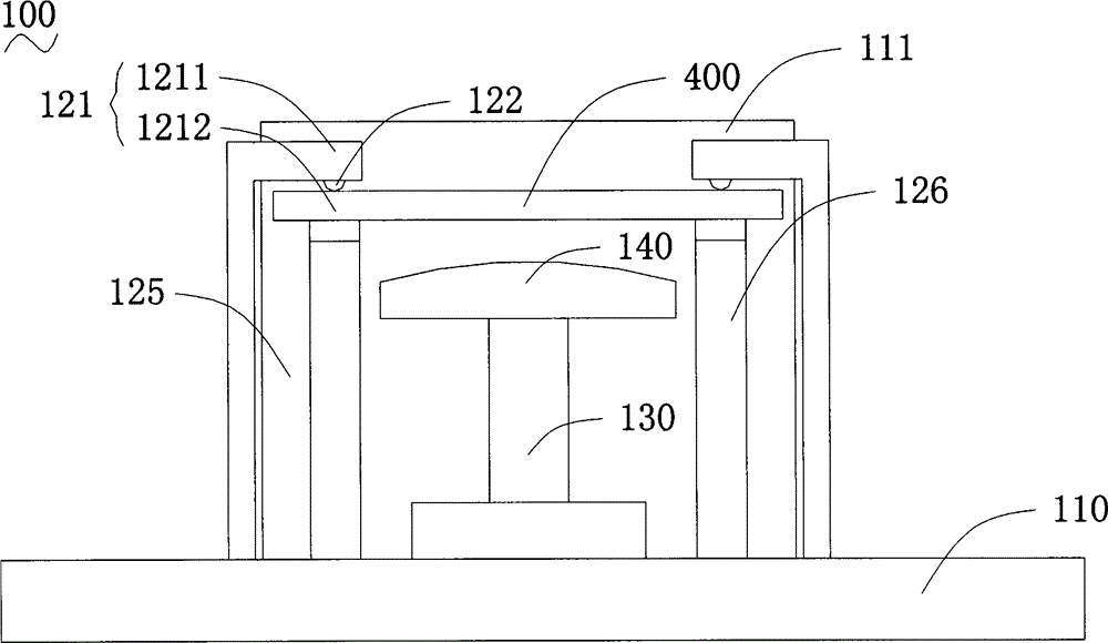
[0034] Please refer to figure 1 , Embodiment 1 discloses a bending tester 100, including: a test platform 110 for performing a bending test on a test sample 400, and two bars on the test platform 110 are used to press against the test sample 400 during the test. The load supporting mechanism at both ends extends out of the operating shaft 130 on the test platform, the bending test mold 140 above the operating shaft 130 and the driving mechanism (not shown) for driving the operating shaft 130 .

[0035] Among them, the test sample 400 is mainly strip-shaped parts such as steel plates, rubber plastic plates, and epoxy new material coatings in the oil and gas pipeline industry. Both load supporting mechanisms are equipped with clamps for clamping one end of the test sample 400. The holding structure 121, in this embodiment, the holding structure 121 is a pair of oppositely arranged movable pads, including a first pad 1211 at the top and a second pad 1212 at the bottom, the first ...

Embodiment approach 2

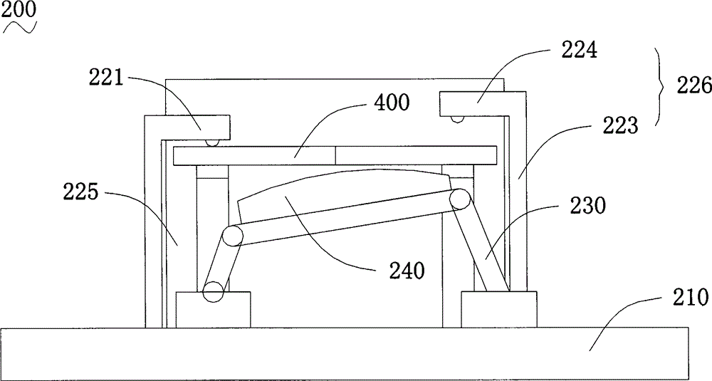
[0043] Please refer to figure 2 , Embodiment 2 discloses a bending tester 200, including: a test platform 210 for performing a bending test on a test sample 400, and two bars on the test platform 210 are used to press against the test sample 400 during the test. The load support mechanism at both ends extends out of the operating shaft 230 on the test platform, the bending test mold 240 above the operating shaft 230 and the driving mechanism (not shown) for driving the operating shaft 230 .

[0044] The difference from Embodiment 1 is that the above two load supporting mechanisms include a first load supporting mechanism 225 and a second load supporting mechanism 226 , and the second load supporting mechanism 226 is higher than the first load supporting mechanism 225 .

[0045] The first load supporting mechanism 225 is provided with a clamping structure 221 for clamping one end of the test sample 400. In this embodiment, the clamping structure 221 can be similar to the clamp...

Embodiment approach 3

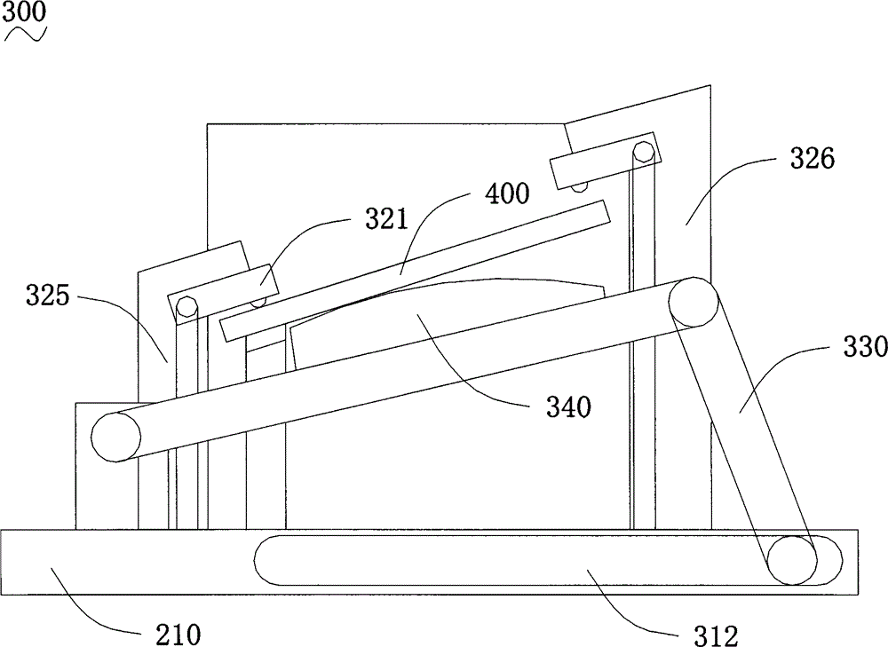
[0049] Please refer to image 3 , Embodiment 3 discloses a bending tester 300, including: a test platform 310 for performing a bending test on a test sample 400, and two bars on the test platform 310 are used to press against the test sample 400 during the test. The load support mechanism at both ends extends out of the operating shaft 330 on the test platform, the bending test mold 340 above the operating shaft 330 and the driving mechanism (not shown) for driving the operating shaft 330 . Wherein, the second load supporting mechanism 326 is higher than the first load supporting mechanism 325 , and the first load supporting mechanism 325 is provided with a clamping structure 321 for clamping one end of the test sample 400 .

[0050] The difference from Embodiment 2 is that the operating shaft 330 is a two-bar linkage mechanism, wherein a guide groove 312 is provided on the test platform 310, and one end of one linkage mechanism is arranged in the guide groove, and can be Und...


PUM


Abstract

The invention relates to a bending tester. The bending tester comprises a testing platform, two load supporting mechanisms, an operation shaft rod arranged on the testing platform, a bending testing mold arranged on the upper portion of the operation shaft rod, and a driving mechanism connected with the operation shaft rod and used for driving the operation shaft rod. At least one load supporting mechanism is provided with a clamping structure used for clamping one end of a testing sample, when the driving device drives the bending testing mold to move, the two ends of the testing sample tightly abut against the two load supporting mechanisms respectively, and the testing sample has bending deformation under the action of the bending testing mold. According to the bending tester, no additional external force factor is introduced in the whole testing process, the texture of the surface of the sample cannot be influenced after a bending resistance test, and a true result after the test can be restored.

Description

technical field [0001] The invention relates to a bending tester for performing a bending resistance test on samples such as steel plates, rubber plastic plates and epoxy new material coatings in the oil and gas pipeline industry, in particular to a bending tester. Background technique [0002] Please refer to figure 1 , is a schematic diagram of the basic structure of a traditional bending tester, which includes: a hydraulic component, a first bending measurement mold located on the hydraulic component, a second bending measurement mold located on the first bending measurement mold and, located on A pair of sample baffles on the first bending measuring mold and the second bending measuring mold, wherein the first bending measuring mold matches the second bending measuring mold, between the first bending measuring mold and the second bending measuring mold There is also a loading space for loading the sample to be tested. [0003] During the use of the above-mentioned bend...

Claims


Application Information

Patent Timeline
IPC IPC(8): G01N3/20
Inventor 孙镇曾昌贤
Owner HILONG ANTI CORROSION TECH ENG TAICANG
Why Eureka
Try Eureka