Magnetic sensor

一种磁传感器、磁场的技术,应用在磁传感器领域,能够解决MR元件磁阻变化率下降、自由层矫顽力增加、MR元件线性变差等问题

Active Publication Date: 2016-08-24
TDK CORPARATION
View PDF8 Cites 13 Cited by
  • Summary
  • Abstract
  • Description
  • Claims
  • Application Information

AI Technical Summary

Problems solved by technology

The first problem is that the free layer has magnetic anisotropy due to the exchange coupling between the free layer and the antiferromagnetic layer. As a result, the coercive force of the free layer increases, and the linearity of the response of the MR element to the magnetic field of the object may deteriorate.
The second problem is that the atoms constituting the antiferromagnetic layer, such as Mn in Mn-based antiferromagnetic materials such as IrMn, diffuse in the free layer, and as a result, the magnetoresistance change rate of the MR element may decrease.

Method used


Image

  • Magnetic sensor
  • Magnetic sensor
  • Magnetic sensor

Examples


no. 1 approach

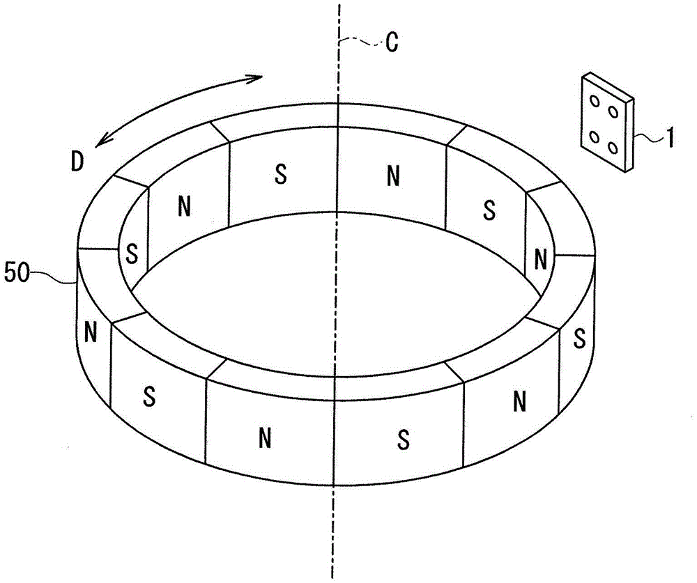
[0032] Hereinafter, embodiments of the present invention will be described with reference to the drawings. First, refer to figure 1 , an example of a magnetic sensor system including the magnetic sensor according to the first embodiment of the present invention will be described. figure 1 It is a perspective view showing the structure of the magnetic sensor system of this embodiment. figure 1 The illustrated magnetic sensor system includes the magnetic sensor 1 of the present embodiment and a rotation scale 50 that generates a magnetic field of an object detected by the magnetic sensor 1 . The rotary scale 50 rotates along a rotation direction D around a predetermined central axis C in conjunction with an unillustrated operating body that rotates. As a result, the relative positional relationship between the rotary scale 50 and the magnetic sensor 1 changes in the rotational direction D. As shown in FIG. The magnetic sensing system detects physical quantities related to the...

no. 2 approach

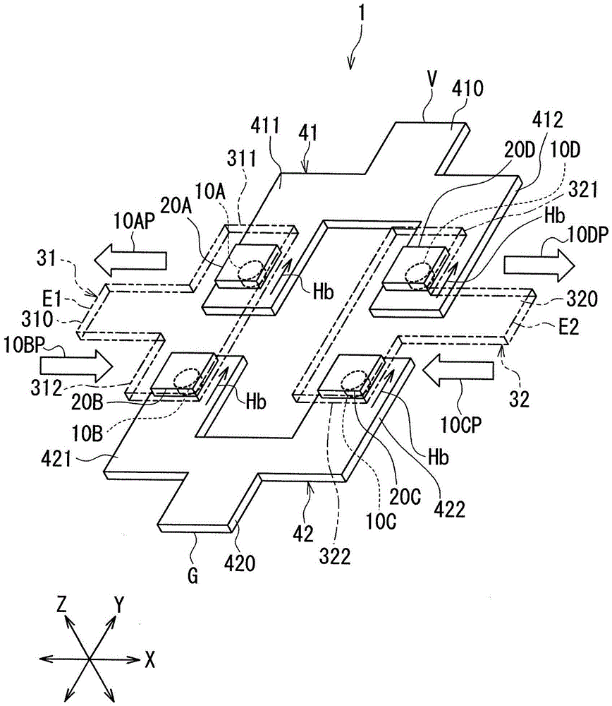
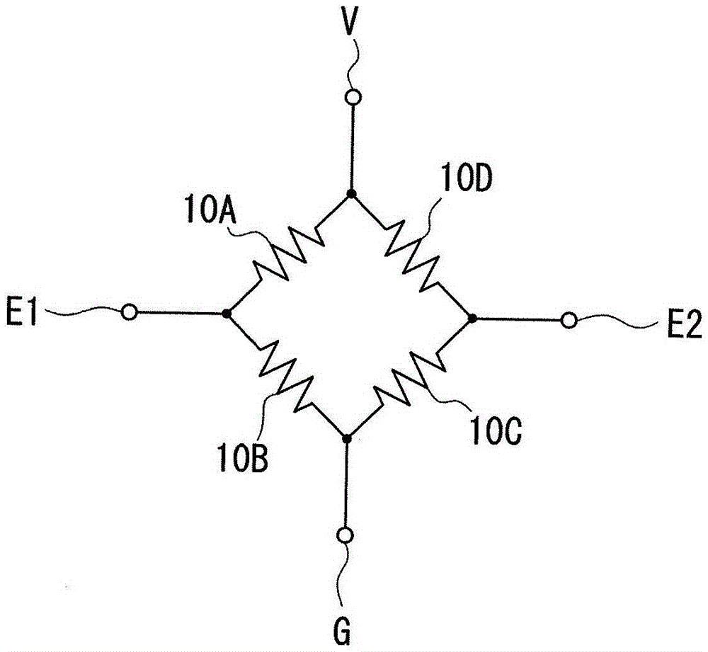
[0087] Next, refer to Figure 13 , the second embodiment of the present invention will be described. Figure 13 It is an enlarged side view showing a part of the magnetic sensor of this embodiment. The magnetic sensor 1 of the present embodiment includes eight MR elements 10, four bias magnetic field generators 20, a substrate not shown, two upper electrodes (first electrodes) 30, and two lower electrodes (second electrodes). 40. In this embodiment, two MR elements 10 connected in parallel via upper electrode 30 and lower electrode 40 are arranged at respective positions of MR elements 10A, 10B, 10C, and 10D described in the first embodiment.

[0088] In the present embodiment, the two MR elements 10 connected in parallel are arranged such that at least a part of each of the two MR elements 10 is contained in the space S defined by the corresponding bias magnetic field generator 20 . The magnetization directions of the magnetization fixed layers 13 in the two MR elements 10...


PUM


Abstract

A magnetic sensor includes an MR element and a bias magnetic field generation unit. The MR element includes a magnetization pinned layer, a nonmagnetic layer and a free layer stacked along Z direction. The bias magnetic field generation unit includes a first antiferromagnetic layer, a ferromagnetic layer and a second antiferromagnetic layer stacked along the Z direction. The bias magnetic field generation unit has a first end face and a second end face located at opposite ends in the Z direction. The MR element is placed such that the entirety of the MR element is contained in a space formed by shifting an imaginary plane equivalent to the first end face of the bias magnetic field generation unit away from the second end face along the Z direction.

Description

technical field [0001] The present invention relates to a magnetic sensor including a magnetic detection element and a bias magnetic field generator for generating a bias magnetic field applied to the magnetic detection element. Background technique [0002] In recent years, magnetic sensor systems for detecting physical quantities related to rotational motion or linear motion of a moving body have been used in various applications. Generally, a magnetic sensing system includes a scale and a magnetic sensor, and the magnetic sensor generates a signal related to the relative positional relationship between the scale and the magnetic sensor. [0003] A magnetic sensor includes a magnetic detection element for detecting a magnetic field as a detection target. Hereinafter, a magnetic field to be detected is referred to as a target magnetic field. Japanese Patent Application Publication No. 2003-215145, Japanese Patent Application Publication No. 2008-151759, and Japanese Paten...

Claims


Application Information

Patent Timeline
Patent Type & Authority Applications(China)
IPC IPC(8): G01R33/02G01P3/44G01B7/00
CPCG01B7/003G01P3/44G01R33/02G01R33/093
Inventor 驹﨑洋亮
Owner TDK CORPARATION
Why Eureka
Try Eureka