
A capacitive touch screen

A capacitive touch screen and conductive substrate technology, applied in the electronic field, can solve problems such as poor connection, wrong insertion by users, and occupation of capacitive touch screen space, and achieve the effect of saving space

Active Publication Date: 2019-08-16
江苏华科创智技术有限公司
View PDF4 Cites 0 Cited by
  • Summary
  • Abstract
  • Description
  • Claims
  • Application Information

AI Technical Summary

Problems solved by technology

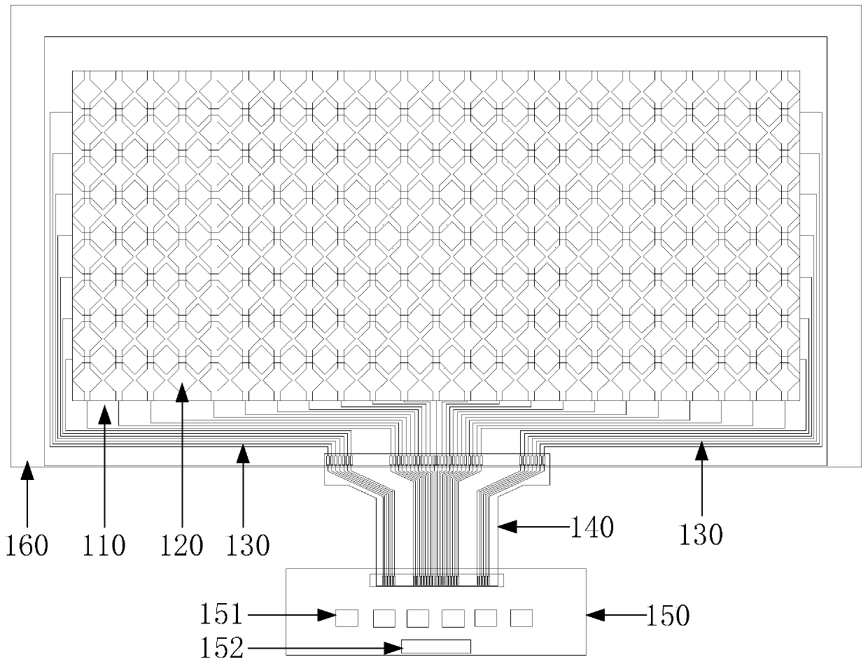
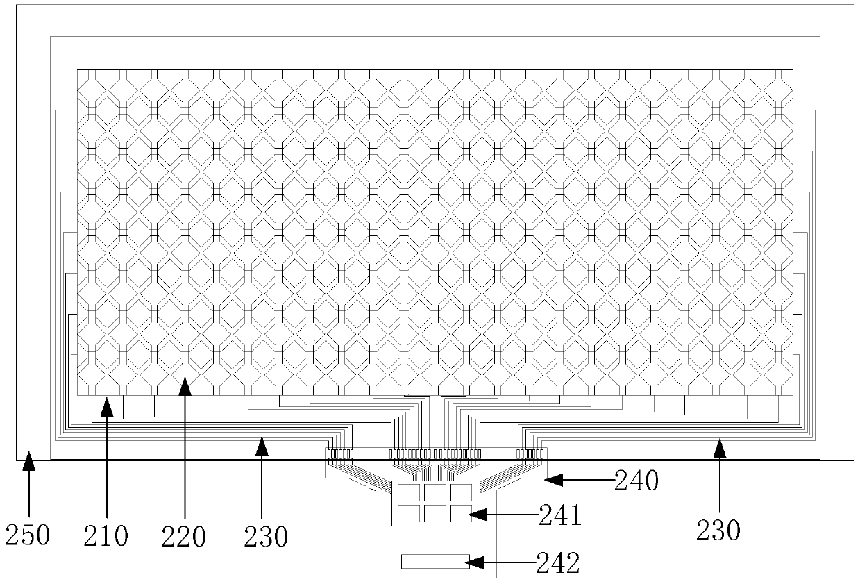
from figure 2 It can be seen that the signal transmission lines 230 are multiple, uniformly and densely arranged around the edge of the conductive substrate 210, so that the capacitive touch screen needs to set a large space around the conductive substrate for wiring, which not only takes up a lot of space, but also Moreover, there are many connection parts in the connection process of the signal transmission line, which is easy to cause poor connection.
In addition, when the user plugs the connectors of each wiring, strong professional knowledge is required to operate, otherwise, due to too many wiring and connectors, it is easy to cause the user to insert the wrong connector.
[0006] from figure 1 and figure 2 It can be seen that the existing capacitive touch screen needs to arrange multiple signal transmission lines during the electrical connection process between the conductive substrate and the IC, which occupies a large amount of space in the capacitive touch screen during the wiring process, and multiple connection parts are connected through multiple signal output lines , which can easily lead to poor contact, and due to excessive wiring and connectors, it is easy to cause users to insert wrongly

Method used


Image

  • A capacitive touch screen
  • A capacitive touch screen
  • A capacitive touch screen

Examples


Embodiment Construction

[0016] The following will clearly and completely describe the technical solutions in the embodiments of the present invention with reference to the accompanying drawings in the embodiments of the present invention. Obviously, the described embodiments are only some, not all, embodiments of the present invention. Based on the embodiments of the present invention, all other embodiments obtained by persons of ordinary skill in the art without making creative efforts belong to the protection scope of the present invention.

[0017] In describing the present invention, it is to be understood that the terms "central", "lateral", "upper", "lower", "left", "right", "vertical", "horizontal", "top", The orientation or positional relationship indicated by "bottom", "inner", "outer", etc. is based on the orientation or positional relationship shown in the drawings, and is only for the convenience of describing the present invention and simplifying the description, rather than indicating or...


PUM


Abstract

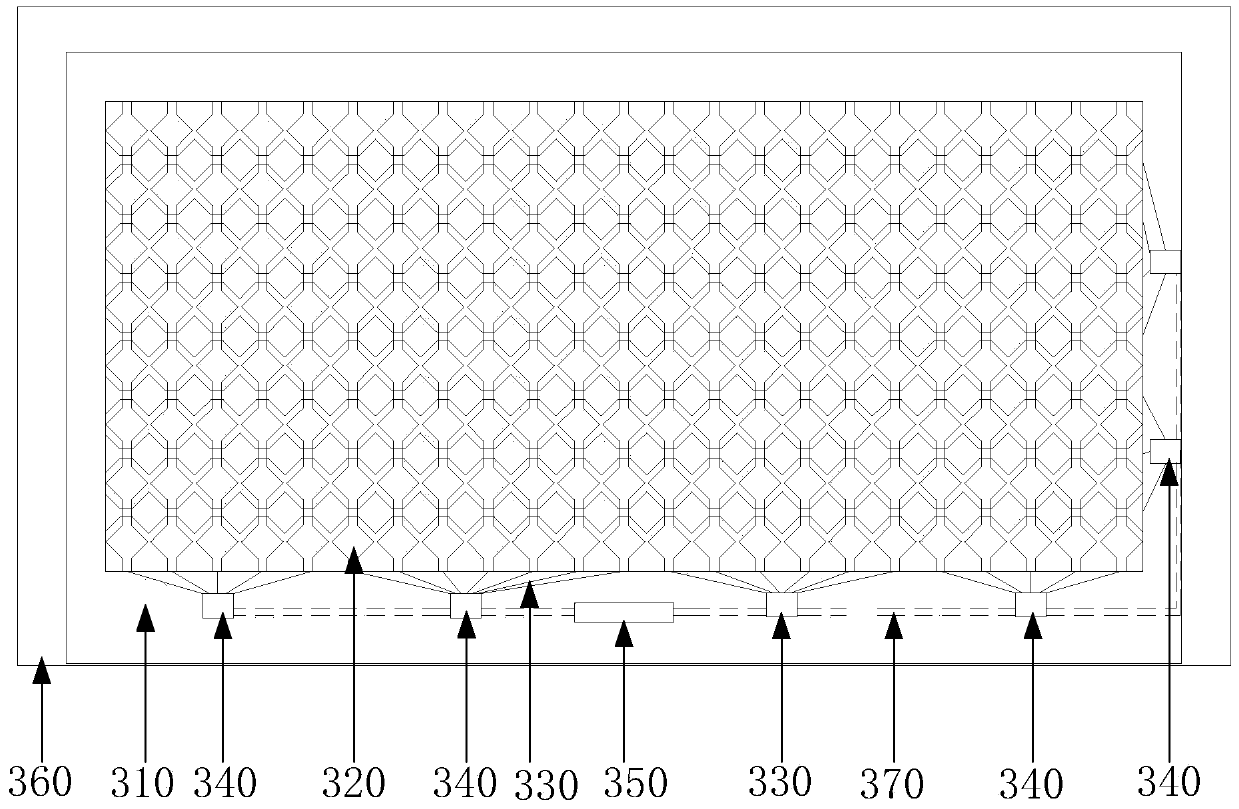
The invention discloses a capacitive touch screen. The capacitive touch screen comprises a conductive substrate and induction channels formed in the surface of the conductive substrate. The multiple induction channels are formed in the surface of the conductive substrate at intervals, and a plurality of control ICs are arranged on the edge of the conductive substrate, connected with the conductive substrate through signal transmission lines respectively and connected to a signal output interface through a connecting line. According to the capacitive touch screen, as the multiple control ICs are directly arranged on the edge of the conductive substrate and are connected, in the process that the conductive substrate is electrically connected with the control ICs through the signal transmission lines, it can be achieved that the control ICs are electrically connected with the conductive substrate only through the short-and-small signal transmission lines, and space on the periphery of the conductive substrate is saved.

Description

technical field [0001] The invention relates to the field of electronic technology, in particular to a capacitive touch screen. Background technique [0002] The touch screen is a simple, convenient and natural human-computer interaction device, which has been widely used in various places. There are many types of touch screens, which mainly include resistive, capacitive, infrared and surface acoustic wave according to the principles. Among them, the capacitive touch screen uses the induced current generated by the capacitance change generated by the electrostatic combination between the electrode on the glass substrate and the human body to detect the coordinates of the touched position. The induction principle uses a voltage to act on the four corners of the screen sensing area and forms a fixed electric field. When the finger touches the screen, the electric field can cause a current. With the help of the controller, the contact can be calculated according to the ratio o...

Claims


Application Information

Patent Timeline
Patent Type & Authority Patents(China)
IPC IPC(8): G06F3/044
CPCG06F3/044
Inventor 黄良杰
Owner 江苏华科创智技术有限公司
Learn More