
Deposit and withdrawal opening mechanism

A deposit and withdrawal port and deposit technology, applied in the direction of handling coins or valuable banknotes, devices and instruments that accept coins, etc., can solve the problems of low utilization rate, waste, high manufacturing cost, etc., achieve simple and convenient installation, and ensure reliability , the effect of increasing the volume

Pending Publication Date: 2016-08-24
广州智清电子科技有限公司
View PDF1 Cites 10 Cited by
  • Summary
  • Abstract
  • Description
  • Claims
  • Application Information

AI Technical Summary

Problems solved by technology

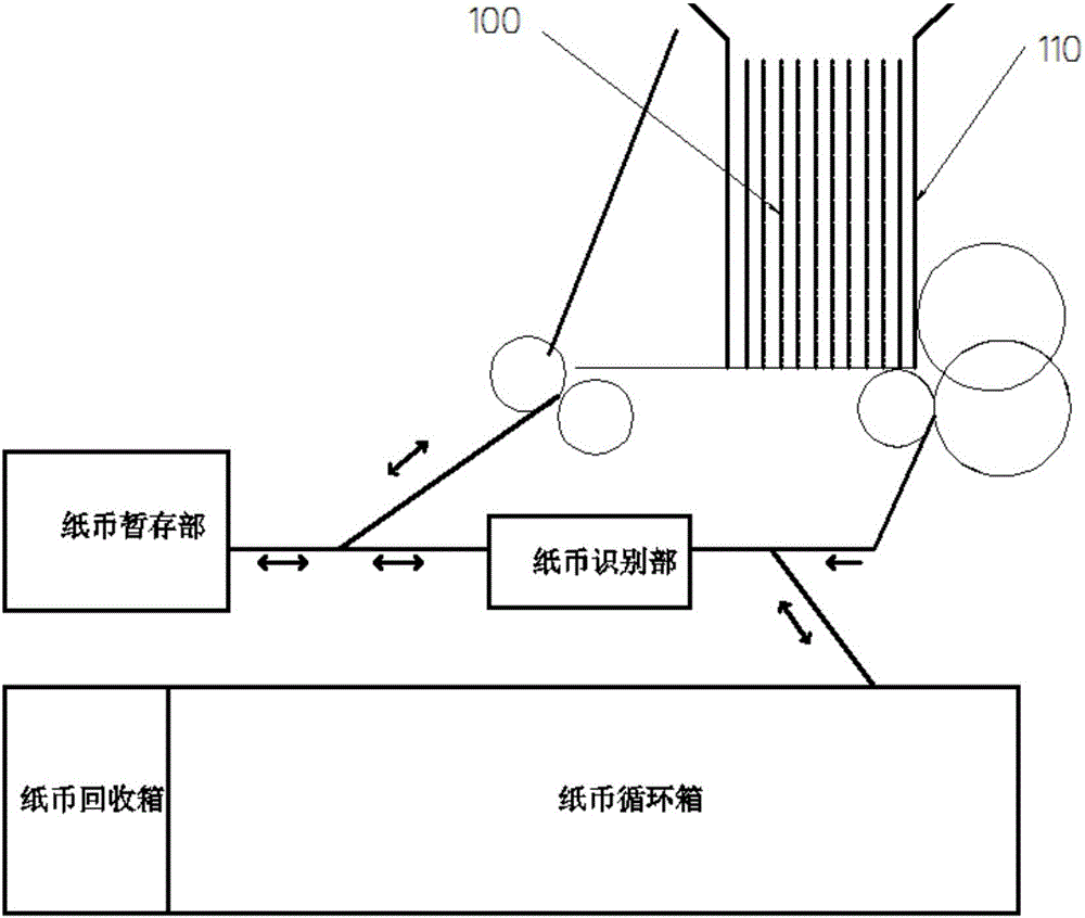
However, this technology will inevitably increase the complexity of stacking banknotes and affect the effect of stacking banknotes. Especially when the withdrawn banknotes are of different widths and sizes, the reliability of this stacking scheme is not high.
The separation component 104 is one of the most precise parts of the cash deposit and withdrawal device, and its manufacturing cost is relatively high. However, the integrated separation component 104a of this technical solution is only used when the user forgets the banknotes, and the usage rate is extremely low, so the installation cost is relatively high. The components are obviously wasteful
At the same time, the addition of the new banknote pressing plate 102a will also cause the problem that the user experience is affected, because the two layers of banknote pressing plates are superimposed together, even if they are made of very thin steel plates, the user experience when putting banknotes will be affected

Method used


Image

  • Deposit and withdrawal opening mechanism
  • Deposit and withdrawal opening mechanism
  • Deposit and withdrawal opening mechanism

Examples


Embodiment Construction

[0041] The present invention will be described in further detail below in conjunction with the accompanying drawings and specific embodiments.

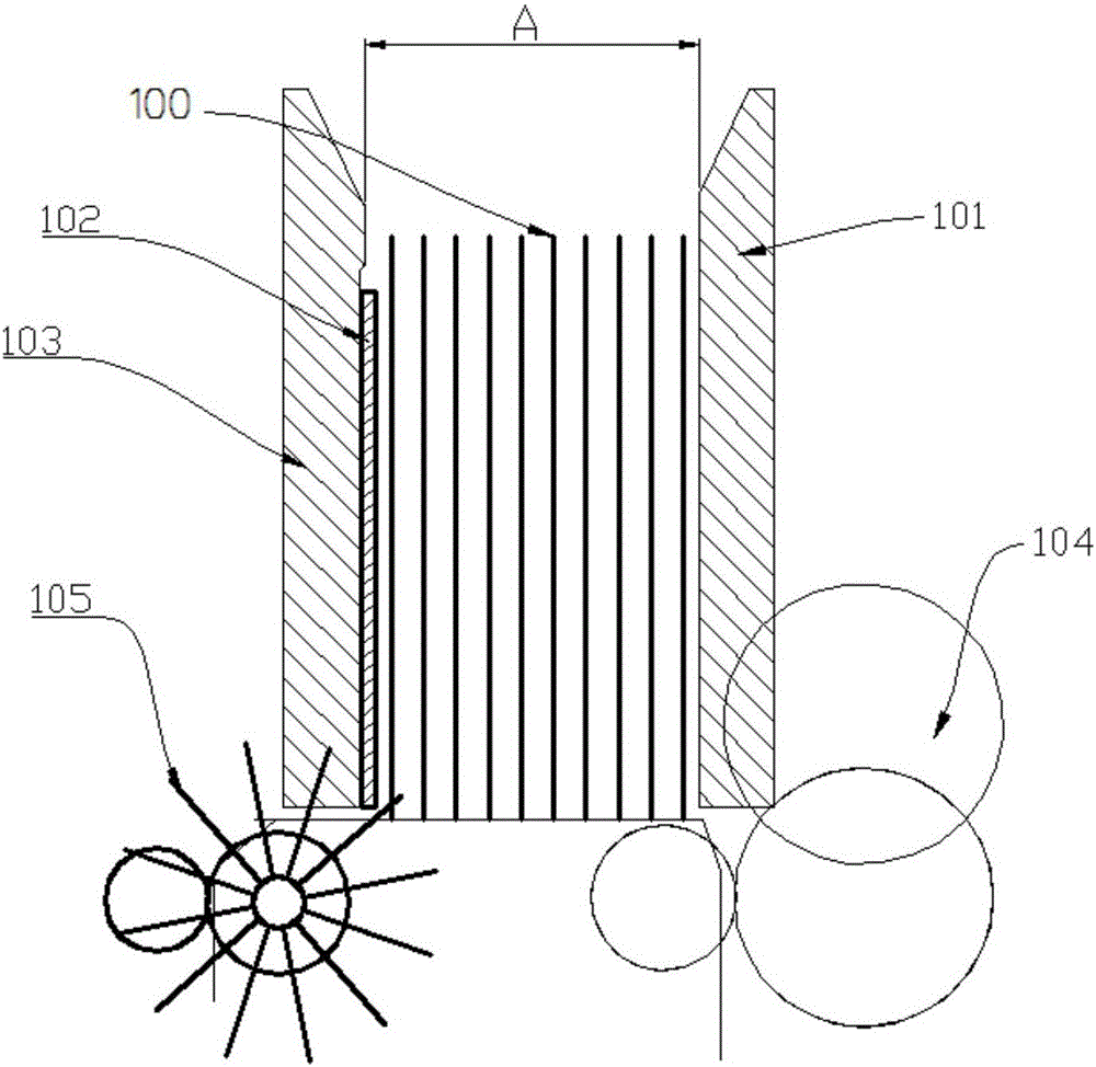
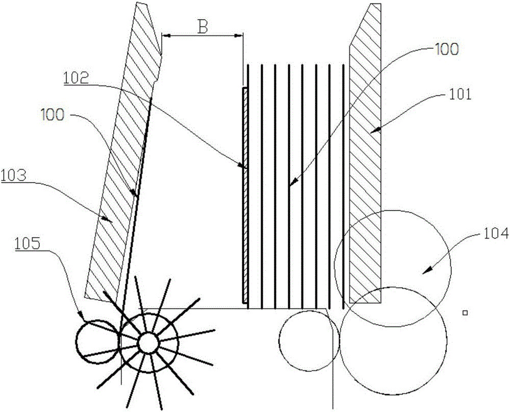
[0042] Such as Figure 5-8 As shown, the present invention provides a deposit and withdrawal mechanism, which includes a front banknote plate 101 , a banknote pressing plate 102 , a rear banknote plate 103 and a banknote retaining module 4 . The front bill plate 101, the bill pressing plate 102 and the rear bill plate 103 can move within a certain range. A banknote separating assembly 104 is disposed near the front bill plate 101 , and a bill stacking assembly 105 is disposed near the rear bill plate 103 . The banknote retaining module 4 is provided with a retractable banknote retaining plate. When depositing, the banknote retaining plate stretches out between the banknote pressing plate 102 and the rear bill plate 103, so as to reduce the space for withdrawing banknotes and block deposits. When other operations are performed, the b...


PUM

PropertyMeasurementUnit
Thicknessaaaaaaaaaa

Abstract

The invention provides a deposit and withdrawal opening mechanism which comprises a front banknote plate, a banknote pressing plate, a rear banknote plate and a banknote blocking module; the front banknote plate, the banknote pressing plate and the rear banknote plate can move within a certain range; a banknote separating component is configured nearby the front banknote plate; a banknote stacking component is configured nearby the rear banknote plate; a telescopic banknote blocking plate is arranged on the banknote blocking module; when the deposit operation is performed, the banknote blocking plate extends out from a part between the banknote pressing plate and the rear banknote plate and is used for reducing the banknote withdrawal space and blocking banknotes withdrawn during deposit; when other operations are performed, the banknote blocking plate retracts to a part above the banknote pressing plate and the rear banknote plate. Compared with the prior art, the deposit and withdrawal opening mechanism provided by the invention has the benefits that on the premise of increasing the single deposit transaction capacity, the banknote withdrawal space is limited by the rear banknote plate and the banknote blocking plate, and the size of the banknote withdrawal space cannot be overlarge, so that the banknotes can be tidily stacked, and meanwhile, the reliability of forgetting recovery can also be ensured. Due to the adoption of a modular design, the deposit and withdrawal opening mechanism can be completely compatible with the conventional deposit and withdrawal equipment.

Description

technical field [0001] The invention belongs to the field of financial automation equipment, and in particular relates to a deposit and withdrawal port mechanism used for deposit and withdrawal integrated equipment. Background technique [0002] ATM provides great convenience for users to withdraw cash, ATM can serve 24 hours a day; and people do not need to line up at the counter to withdraw cash, which greatly reduces the workload of bank tellers. In recent years, with the advancement of technology, the ATM CRS has gradually become the mainstream of self-service equipment. CRS can withdraw the cash deposited by users for other users to withdraw. This cash deposit and withdrawal equipment greatly reduces the need for banks to clear and add cash. The workload, especially when the amount of deposits and withdrawals are relatively consistent, can last for several months without manual intervention, bringing obvious economic benefits to the bank. At present, the deposit and wi...

Claims


Application Information

Patent Timeline
IPC IPC(8): G07D11/00
CPCG07D11/14
Inventor 吴恩张晓生廖任
Owner 广州智清电子科技有限公司
Learn More