
Remote electronic circuit experimental system and experimental method thereof

An electronic circuit and experimental system technology, applied in the field of remote electronic circuit experimental system, can solve the problems of experimental equipment waste, experimental time limit, difference, etc., and achieve the effects of avoiding idle waste, accelerating aging improvement, and flexible experimental time

Inactive Publication Date: 2016-08-24
HEBEI UNIVERSITY OF SCIENCE AND TECHNOLOGY
View PDF7 Cites 1 Cited by
  • Summary
  • Abstract
  • Description
  • Claims
  • Application Information

AI Technical Summary

Problems solved by technology

[0002] In the experimental class, students can use relevant equipment to conduct electronic experiments in the laboratory. The relevant equipment includes signal source generators, experiment boxes, oscilloscopes, and voltage and current measuring instruments. However, when students are outside the laboratory, they cannot Do the experiment again, not only the experimental time is limited, but also the experimental equipment is wasted during the long-term idle process. The damage to the equipment is particularly serious when it is turned on after a long shutdown. The life of the experimental equipment is generally shortened, and the value of the experimental equipment cannot be fully utilized. The existing experimental systems that are separated from the laboratory are all simulation experiments, not real experiments. There are certain differences from real experiments, which are of limited help to the experimental level of experimenters. In recent years, with the increasing maturity of remote control technology, it is possible to Development of an electronic circuit experiment system based on remote control technology

Method used


Image

  • Remote electronic circuit experimental system and experimental method thereof

Examples


Embodiment Construction

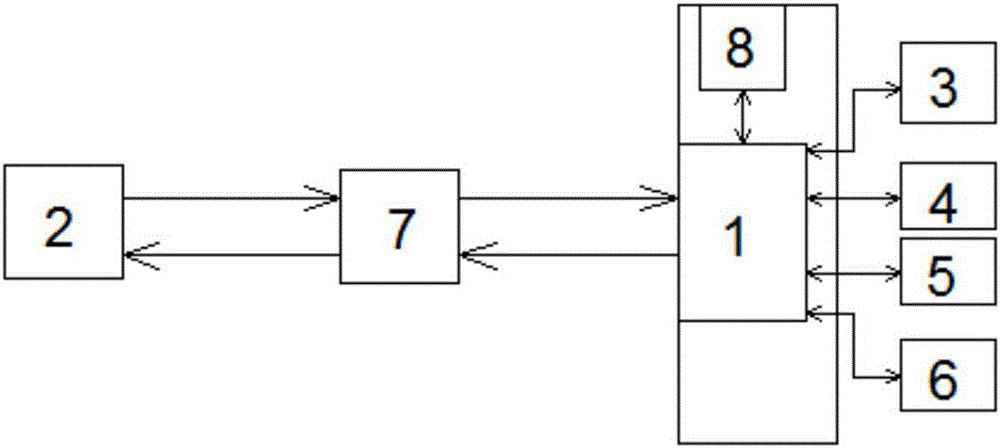
[0016] The invention relates to a remote electronic circuit experiment system and an experiment method thereof. The electronic circuit experiment system includes an experiment box with a processor 1, and controlled switch contacts are added at both ends of each circuit component in the experiment box. The controlled end of the control switch contact is connected to the control end of the processor 1, and a remote client 2, a signal generation circuit 3 connected to the processor 1, a waveform output circuit 4, a display circuit 5, and a current and voltage measurement circuit are added to the system. Circuit 6, the above-mentioned circuit is located outside the experiment box and is connected with the processor 1 in the experiment box, and performs signal generation, waveform output, display and signal simulation of current and voltage measurement respectively, and the remote client 2 communicates with the processor by means of the network and communication interface 1 Establis...


PUM


Abstract

The invention relates to a remote electronic circuit experimental system and an experimental method thereof, and belongs to the technical field of electronic experimental equipment. The experimental system comprises an experimental box with a processor, controlled switch contacts are additionally arranged at the two ends of each circuit component in the experimental box, the controlled ends of the controlled switch contacts are all connected with the control end of the processor, the system is further provided with a remote user end, as well as a signal generating circuit , a waveform output circuit, a display circuit, and a current and voltage measuring circuit which are connected with the processor, a remote client end is in communication with the processor in virtue of internet and communication interface, commands sent out by the remote client end are transmitted to the processor through internet, the processor controls the on / off of each controlled switch, the signal generating circuit generates signals, the waveform output circuit and the display circuit display the signals after signal processing, the current and voltage measuring circuit is used for metering an experimental module, metered data is fed back to the remote client end, real time remote experiment is realized, the experiment flexibility is enhanced, and experimental equipment also can be fully used.

Description

technical field [0001] The invention belongs to the technical field of electronic experiment equipment, and in particular relates to a remote electronic circuit experiment system and an experiment method thereof. Background technique [0002] In the experimental class, students can use relevant equipment to conduct electronic experiments in the laboratory. The relevant equipment includes signal source generators, experiment boxes, oscilloscopes, and voltage and current measuring instruments. However, when students are outside the laboratory, they cannot Do the experiment again, not only the experimental time is limited, but also the experimental equipment is wasted during the long-term idle process. The damage to the equipment is particularly serious when it is turned on after a long shutdown. The life of the experimental equipment is generally shortened, and the value of the experimental equipment cannot be fully utilized. The existing experimental systems that are separate...

Claims


Application Information

Patent Timeline
Patent Type & Authority Applications(China)
IPC IPC(8): G09B23/18
CPCG09B23/183
Inventor 蔡明伟睢丙东安兵菊
Owner HEBEI UNIVERSITY OF SCIENCE AND TECHNOLOGY
Learn More