
Emergency lamp switch control system

A switch control system and emergency lighting technology, applied in the field of fire emergency lighting, can solve the problems of unreasonable design of emergency lighting control system, increased design and installation costs, unfavorable unified management of lamps, etc., and achieve strong practical value and market promotion value , Simple structure, cost reduction effect

Inactive Publication Date: 2017-05-31
GUANGZHOU OUSHU ENVIRONMENTAL PROTECTION TECH CO LTD
View PDF0 Cites 2 Cited by
  • Summary
  • Abstract
  • Description
  • Claims
  • Application Information

AI Technical Summary

Problems solved by technology

In the prior art, due to the unreasonable design of the emergency lighting control system, it generally has the following problems: 1. Most of the emergency lights can only be started in the event of a fire, unexpected power failure, etc., and are basically in an idle state at ordinary times. , which will lead to waste of lamps; 2. During construction or installation, an emergency light control system needs to be set independently, which increases the design and installation costs, and is not conducive to the unified management of lamps; 3. The existing emergency light control system has a structure Complicated, high cost and other defects

Method used


Image

  • Emergency lamp switch control system
  • Emergency lamp switch control system

Examples


Embodiment Construction

[0015] The embodiments of the present invention will be described in detail below with reference to the accompanying drawings, but the present invention can be implemented in many different ways defined and covered by the claims.

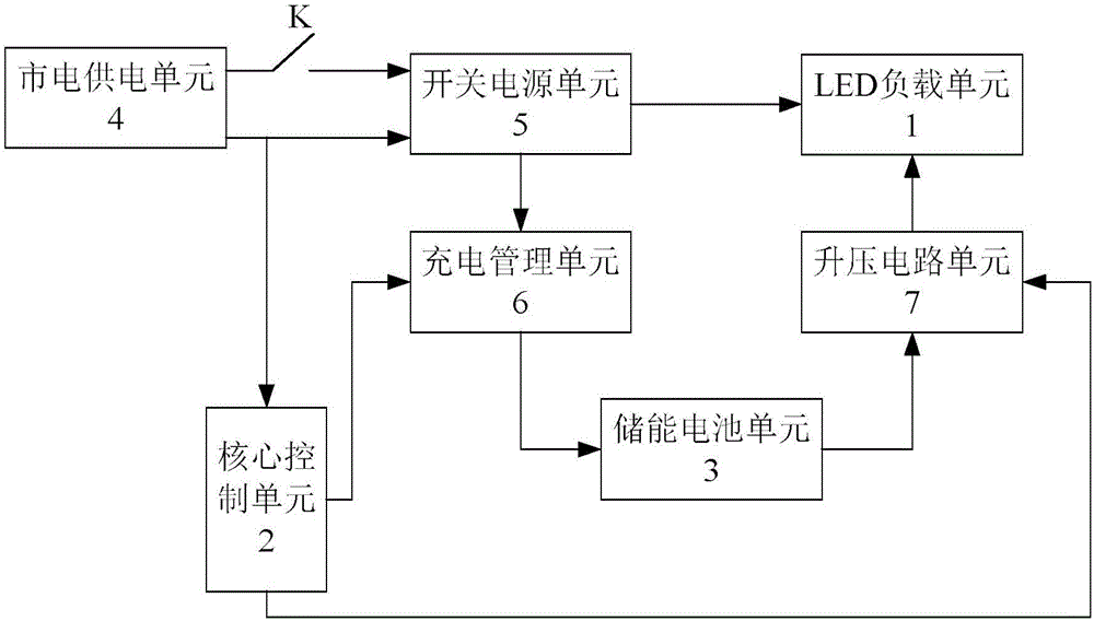
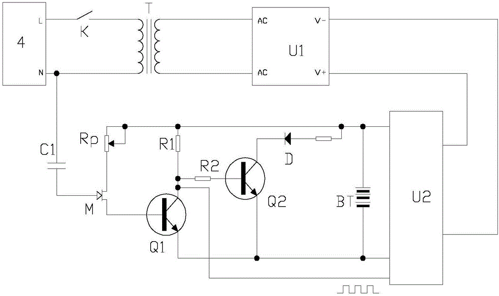
[0016] like figure 1 and figure 2 As shown, an emergency light switch control system provided by the present invention includes an LED load unit 1, a core control unit 2, an energy storage battery unit 3, a mains power supply unit 4 for outputting single-phase alternating current, and a single-phase A switching power supply unit 5 that converts alternating current into direct current, and a charging management unit 6 and a boost circuit unit 7 that are controlled by the core control unit 2 at the same time; wherein, the LED load unit 1 is connected to the output end of the switching power supply unit 5, and the boost circuit The unit 7 is connected between the energy storage battery unit 3 and the LED load unit 1, the charging management unit 6 is...


PUM


Abstract

The invention relates to the technical field of fire emergency lighting, and in particular relates to an emergency lamp switch control system. The system comprises an LED load unit, a core control unit, an energy storage battery unit, a mains power supply unit, a switch power supply unit, and a charging management unit and a boosted circuit unit controlled by the core control unit, wherein a control switch is arranged on a live line or a null line of the mains power supply unit, and a signal detection end of the core control unit is connected with the live line or the null line of the mains power supply unit. According to the system provided by the invention, the core control unit can be used for automatically detecting whether the mains power supply unit can supply power or implement outage normally (comprising normal outage or accident outage), a load can have a function of lighting commonly via the control switch, the energy storage battery can also be called in the case of accident outage to supply power, and thus the load has a function of lighting emergently; a utilization rate of the emergency lamp can be effectively improved, waste of the lamp due to being idle is avoided, and the purposes of being energy-saving and environment-protecting, and reducing cost are achieved.

Description

technical field [0001] The invention relates to the technical field of fire emergency lighting, in particular to an emergency light switch control system. Background technique [0002] As everyone knows, the fire emergency lighting system mainly comprises accident emergency lighting, emergency exit sign and pilot lamp, is after the normal lighting power supply cut off when breaking out of fire, guides trapped personnel to evacuate or launch the fire fighting and rescue action and arrange. In the prior art, due to the unreasonable design of the emergency lighting control system, it generally has the following problems: 1. Most of the emergency lights can only be activated when there is a fire, accidental power failure and other accidents, and they are basically in an idle state at ordinary times. , which will lead to waste of lamps; 2. During construction or installation, an emergency light control system needs to be set independently, which increases the design and installat...

Claims


Application Information

Patent Timeline
Patent Type & Authority Applications(China)
IPC IPC(8): H05B33/08H05B44/00
CPCH05B45/37H05B45/00Y02B20/30
Inventor 方彐云
Owner GUANGZHOU OUSHU ENVIRONMENTAL PROTECTION TECH CO LTD
Learn More