Broadband differential antenna

A differential and antenna technology, applied in the field of wireless communication antennas, can solve the problems of large size and complex structure of broadband microstrip antennas, and achieve the effects of simple structure, small size and easy processing

Inactive Publication Date: 2016-08-24
NANJING UNIV OF SCI & TECH
View PDF5 Cites 6 Cited by
  • Summary
  • Abstract
  • Description
  • Claims
  • Application Information

AI Technical Summary

Problems solved by technology

[0005] In short, the existing problems in the prior art are: the broadband microstrip antenna has a large volume and complex structure

Method used


Image

  • Broadband differential antenna
  • Broadband differential antenna
  • Broadband differential antenna

Examples


Embodiment 1

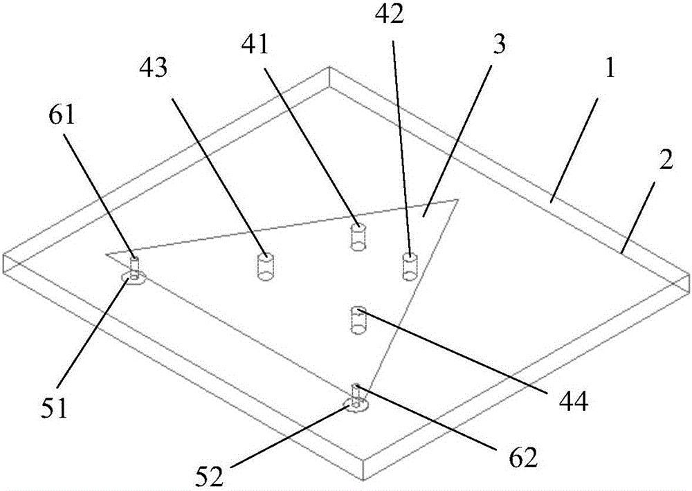
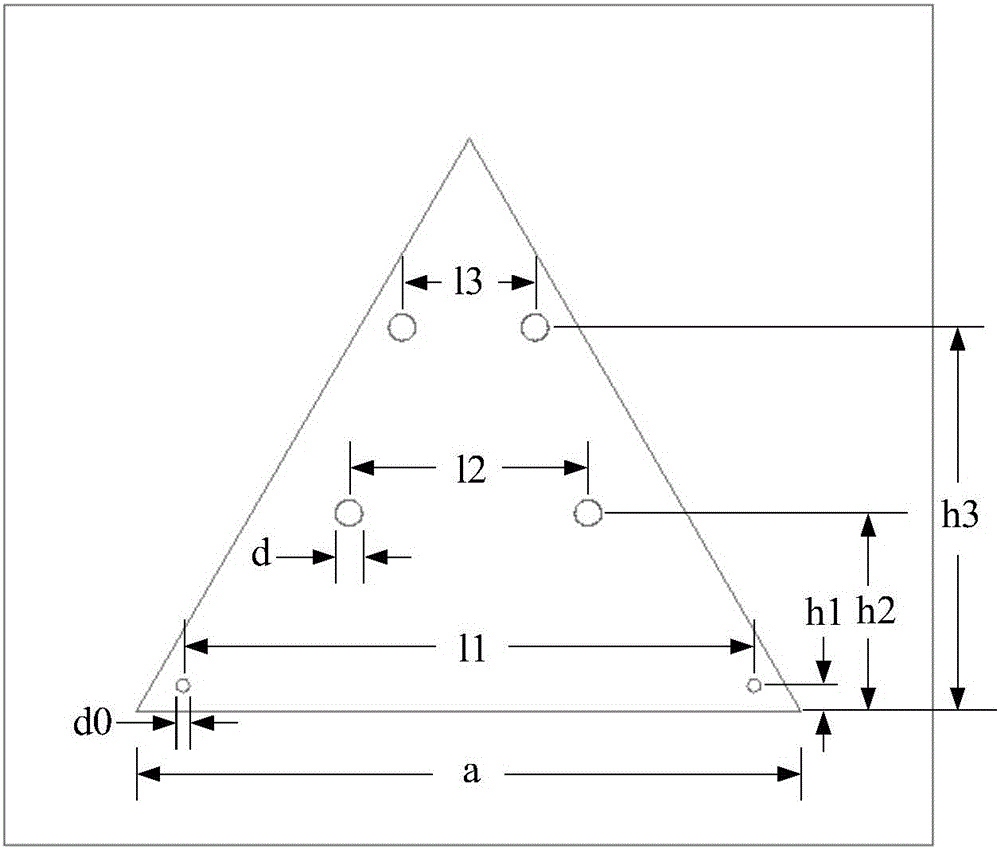
[0029] The structure of an equilateral triangular patch broadband differential antenna loaded with short-circuit pins is as follows: figure 1 As shown, the relevant dimensions and specifications are as follows figure 2 As shown, the dielectric plate used is a Rogers RT / duroid 5880 plate with a dielectric constant of 2.2 and a thickness of 3.175 mm. combine figure 2 , the size parameters of the differential antenna are as follows: a=50mm, d0=1mm, d=2mm, l1=43.1mm, h1=2mm, l2=18mm, h2=15mm, l3=10mm, h3=29.5mm.

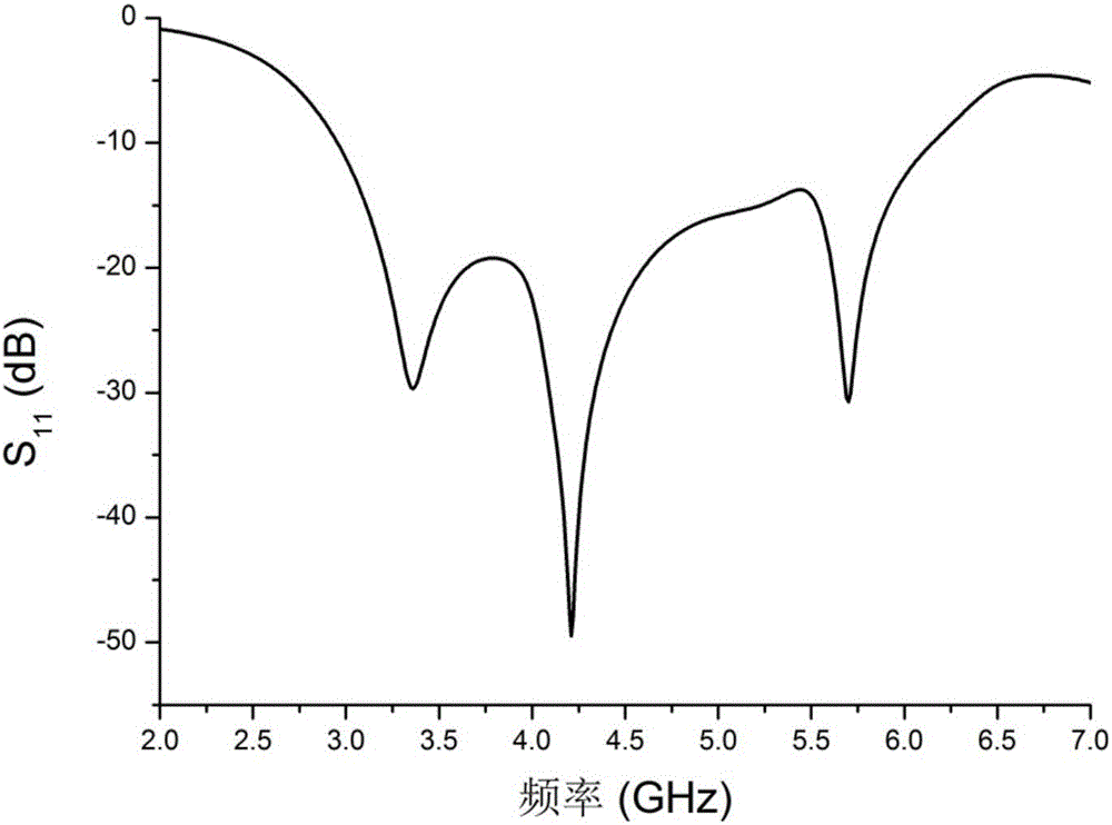
[0030] The differential antenna in this example is modeled and simulated in the electromagnetic simulation software HFSS.13. image 3 is the reflection coefficient simulation diagram in this example. From image 3 It can be seen that the bandwidth of the antenna can cover the frequency band of 2.95-6.15GHz, and the impedance bandwidth is 71.1%, which is significantly increased compared with the general patch antenna.

[0031] Take three frequency points in the pas...


PUM


Abstract

The invention discloses a broadband differential antenna, comprising a dielectric substrate (1), a metal grounding plate (2) attached to the lower surface of the dielectric substrate (1), a metal patch (3) on the upper surface of the dielectric substrate (1) and four shorting pins (41, 42, 43, 44), wherein the shorting pins (41, 42, 43, 44) penetrate through the dielectric substrate (1) to connect the metal patch (3) with the metal grounding plate (2); the antenna further comprises two feed ports (51, 52) and two coaxial feed probes (61, 62), the feed ports (51, 52) are located on the metal grounding plate (2), one end of each of the coaxial feed probes (61, 62) is connected with the metal patch (3), and the other end penetrates through the dielectric substrate (1) and stretches into the feed ports (51, 52). The broadband differential antenna is small in size and simple in structure.

Description

technical field [0001] The invention belongs to the technical field of wireless communication antennas, in particular to a broadband differential antenna with small volume and simple structure. Background technique [0002] The rapid development of wireless communication technology has promoted the need for fully integrated RF front-end products. The integrated RF front-end is usually implemented using differential technology. As one of the key components of the RF front-end, most antennas are designed as single-port devices. The differential antenna has changed the design method of the traditional antenna and directly feeds the differential signal into the two ports of the antenna. It provides a new way to design a highly integrated RF front-end. [0003] Compared with conventional microwave antennas, microstrip antennas have the advantages of small size, light weight, low profile, can run with the carrier, simple manufacture, and low cost, so they are widely used. Micros...

Claims


Application Information

Patent Timeline
Patent Type & Authority Applications(China)
IPC IPC(8): H01Q1/36H01Q1/38H01Q1/48H01Q13/10
CPCH01Q1/36H01Q1/38H01Q1/48H01Q13/10
Inventor 刘倩文邓一静王雪道王建朋
Owner NANJING UNIV OF SCI & TECH
Why Eureka
Try Eureka